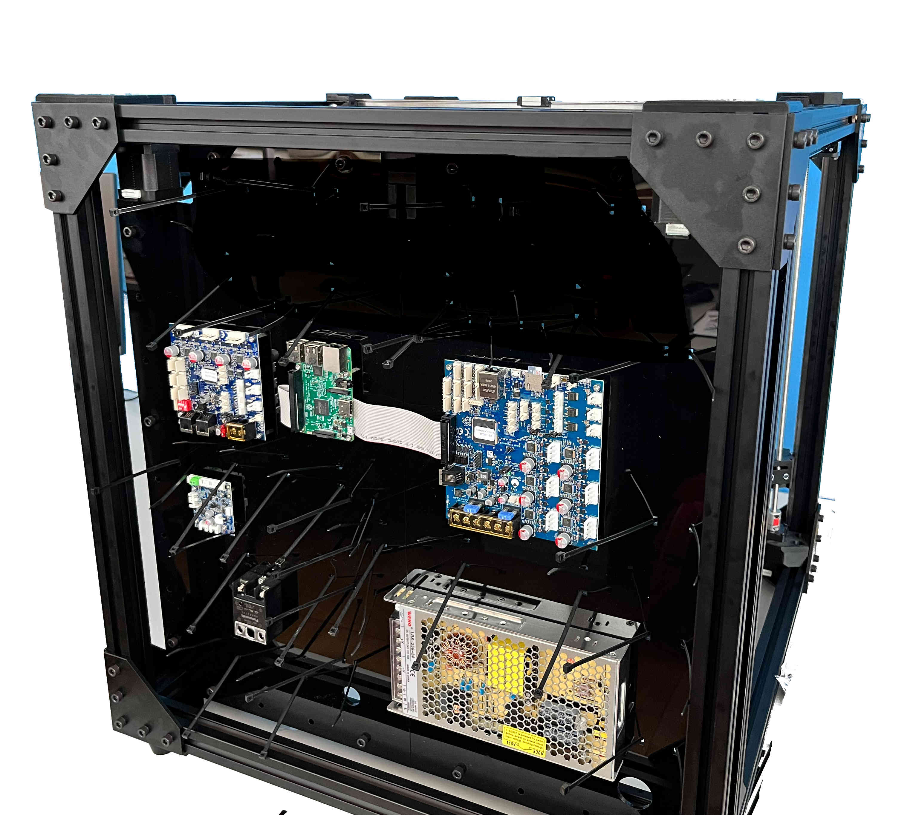
Electronics and Wiring
For the electronics, you will need to crimp your own connectors. We recommend adding quick connectors for the printheads, to make removing the printheads for maintenance easy. In this example, 5x2 DuPont connectors were used for everything but the heater wires, which use a MOLEX style connector. Assuming you have prepared all wires as in the “Crimped Wires” section under “Bill of Materials”, please follow the guide below.
Attention
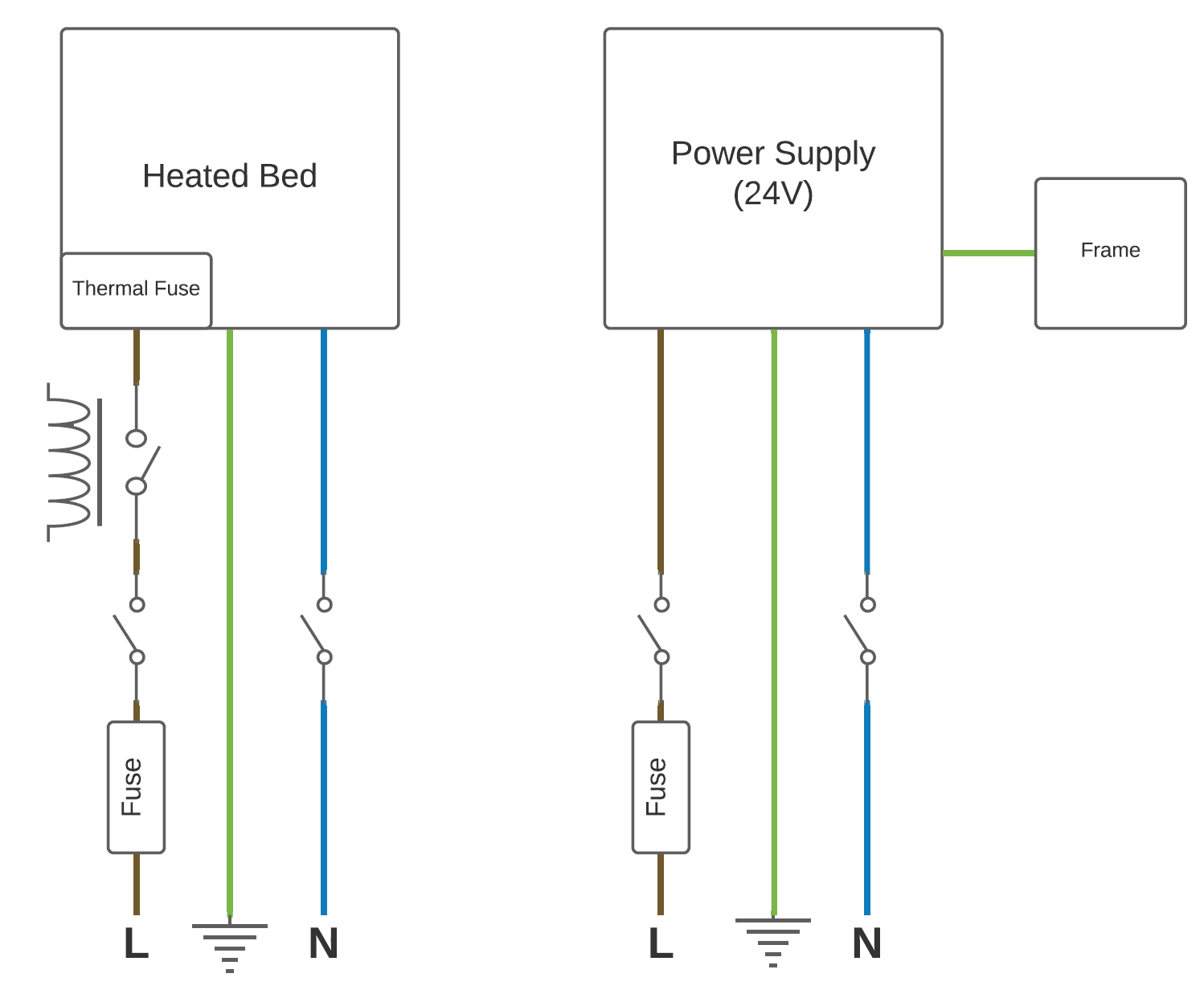
Wiring for the printer also requires some mains wiring. This should only be done by a certified electrician. The plans can be found at the end of this guide.


Note
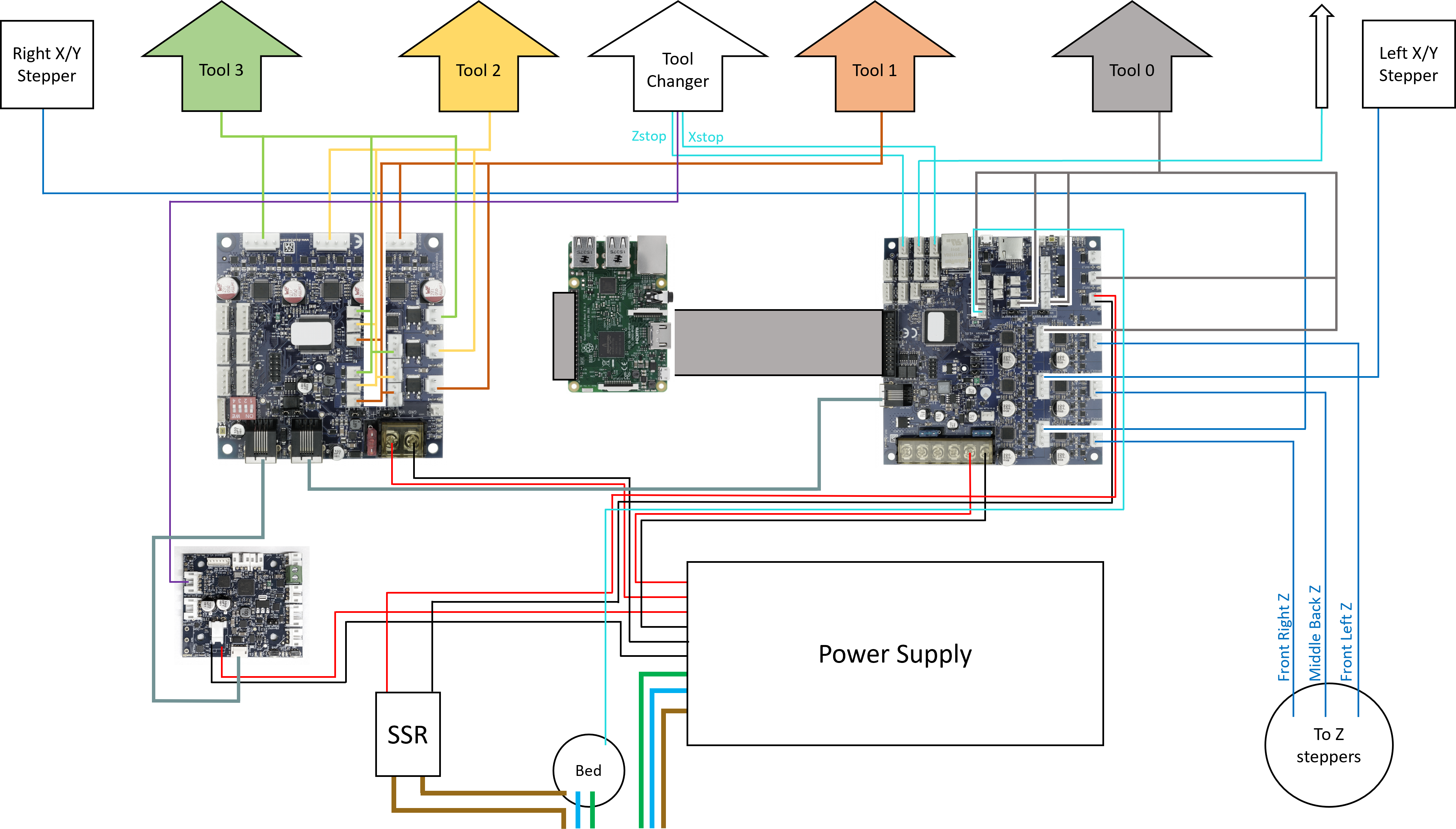
For the following steps please refer to the wiring diagram.

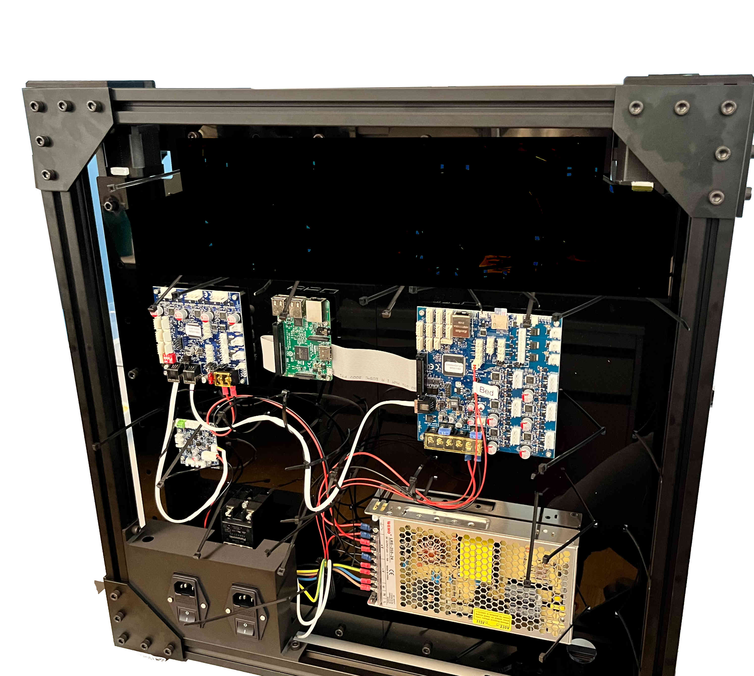
Connect the heater cable and thermistor for the heated bed and the extruders as shown in the wiring diagram. Lastly secure the wires using the zip ties.
Wiring Diagram
Mains Wiring
Danger
Mains voltage can be lethal and should only be handled by a certified electrician!
Danger
Mains voltage can be lethal and should only be handled by a certified electrician!