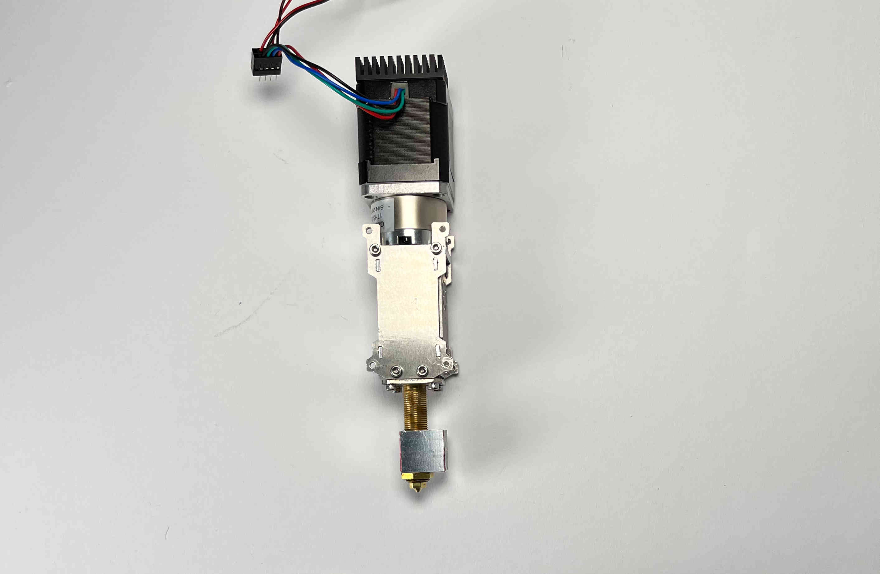
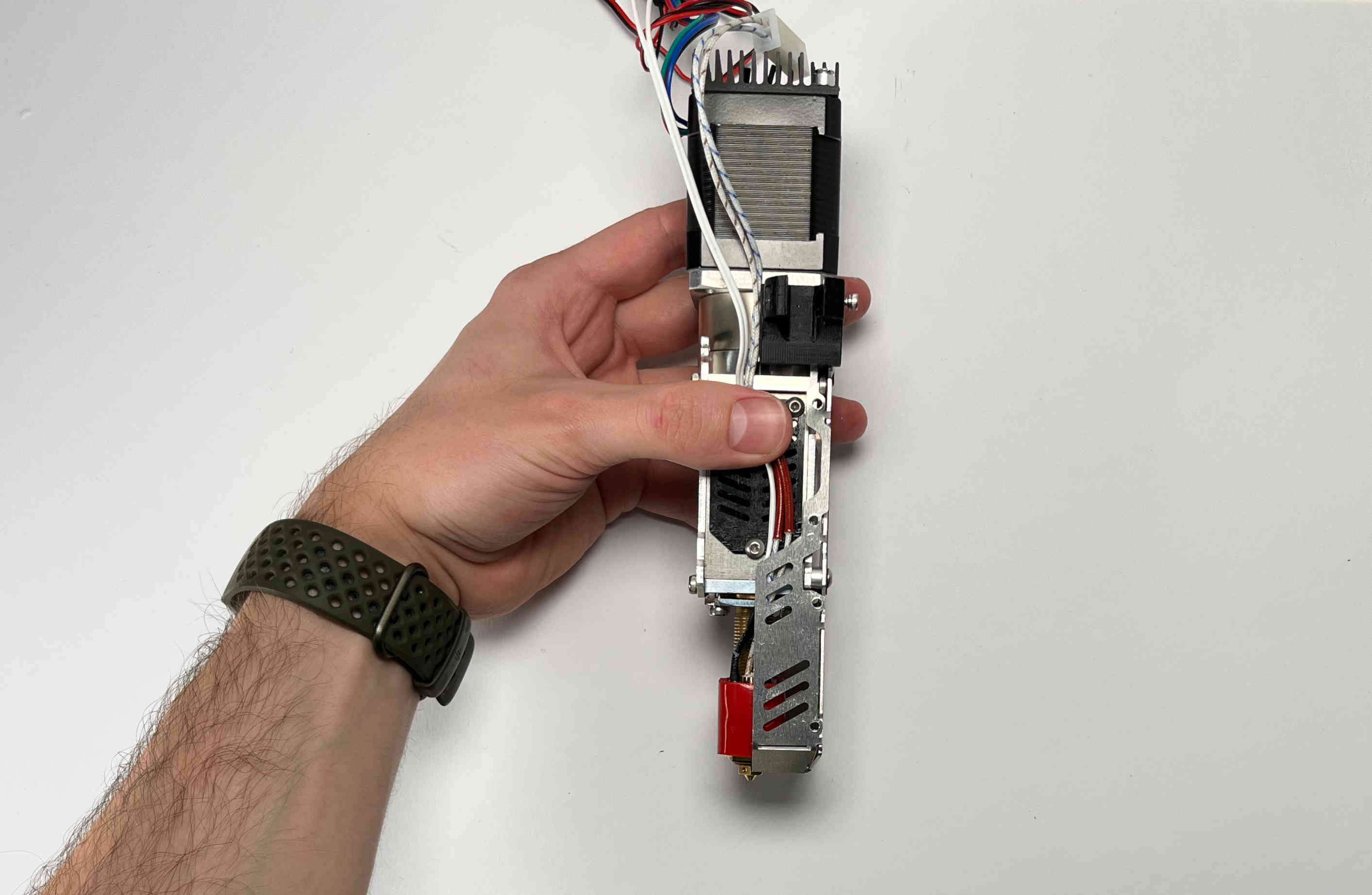
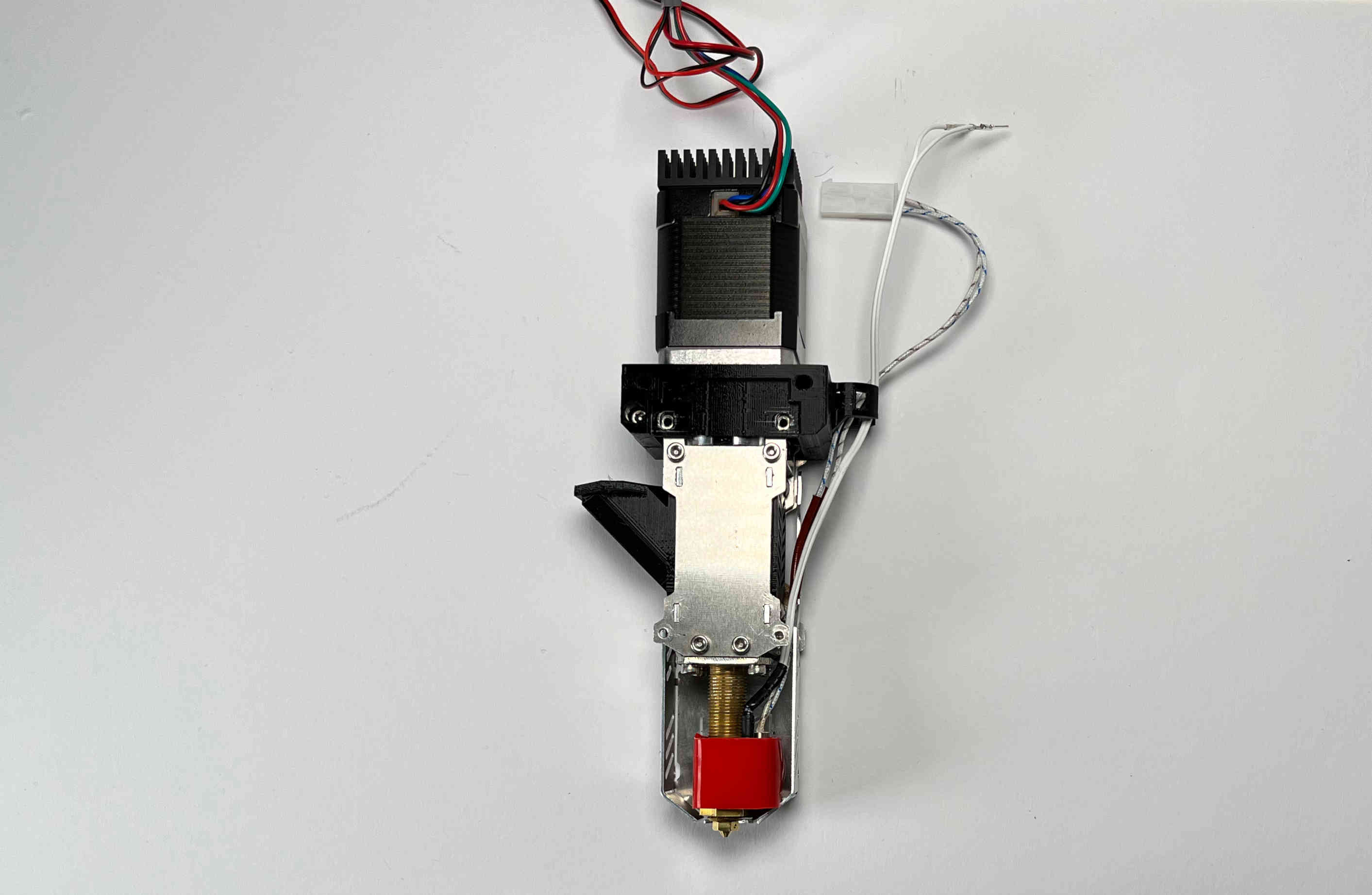
Pellet Extruder V4
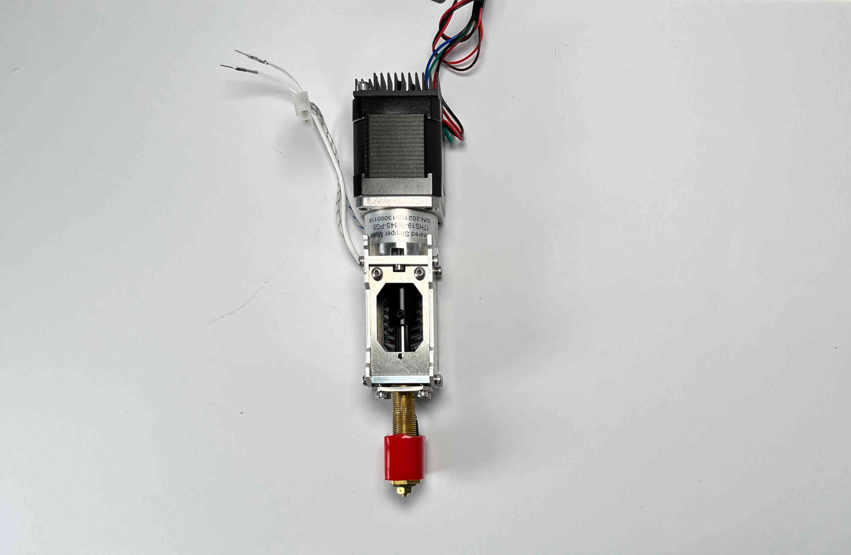
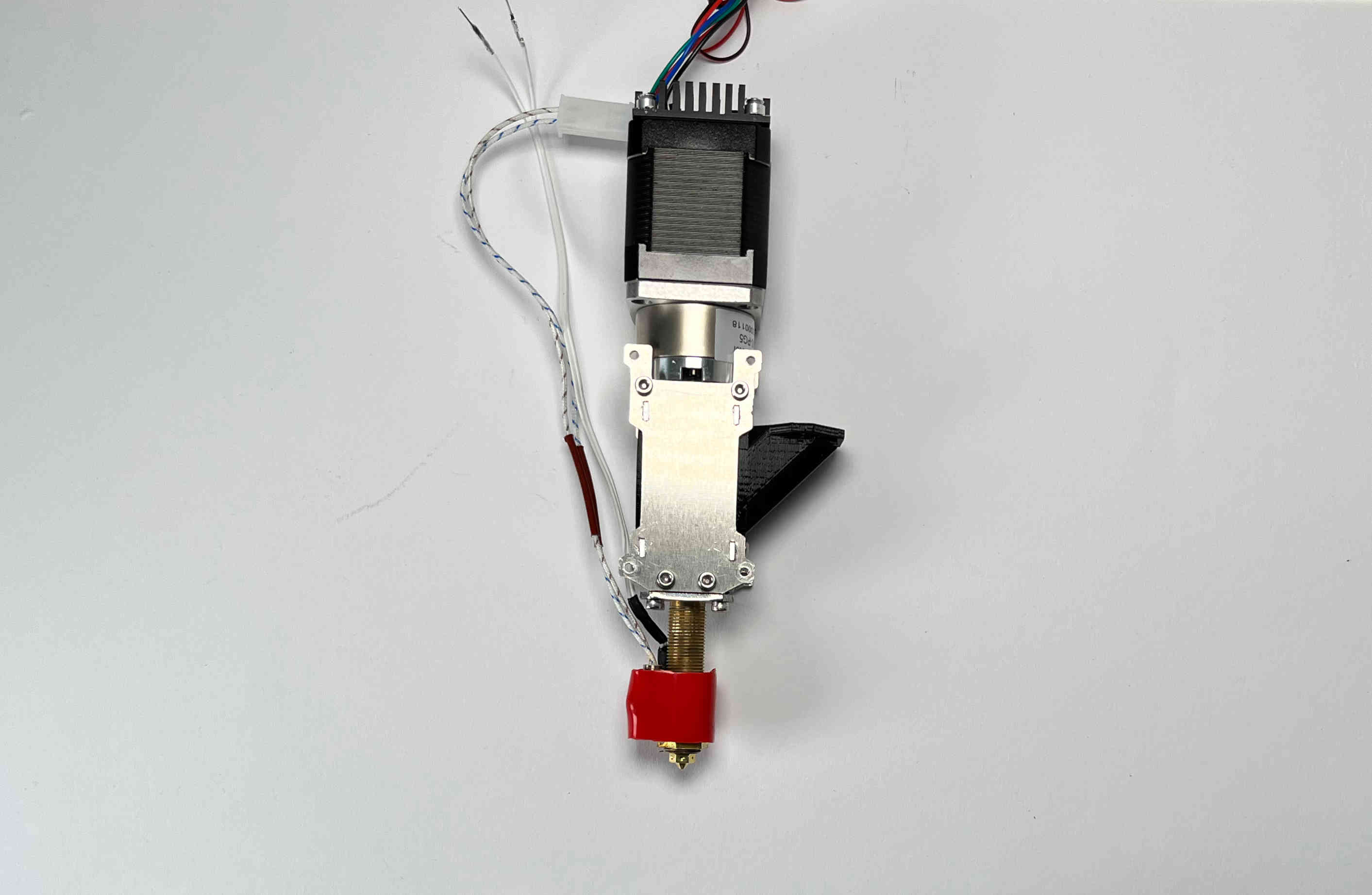
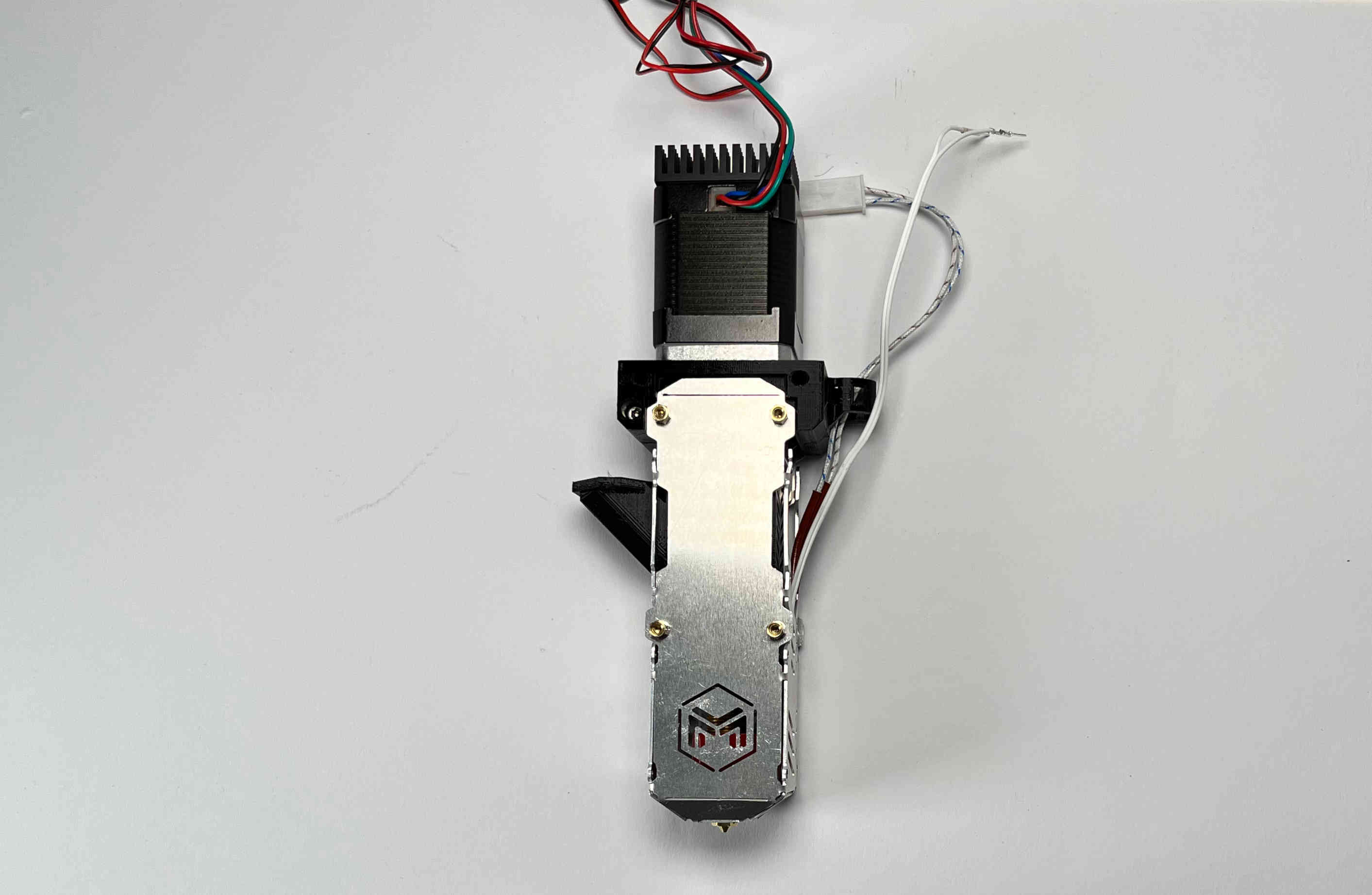
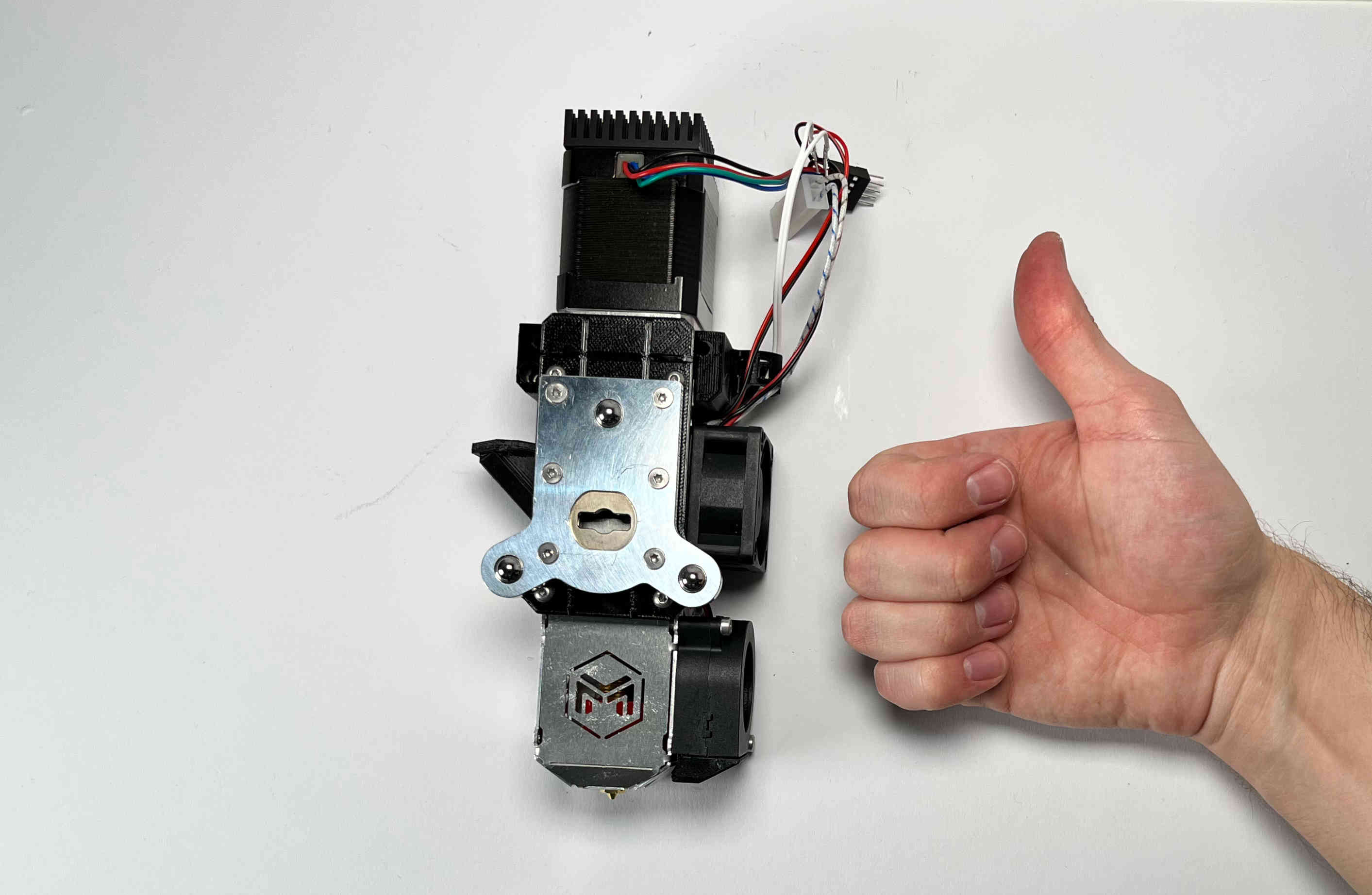
In case your pellet extruder came preassembled please disassemble it until it looks like the one in this image. This can be done intuitively or by following several steps of this build guide backwards.
Heating Element
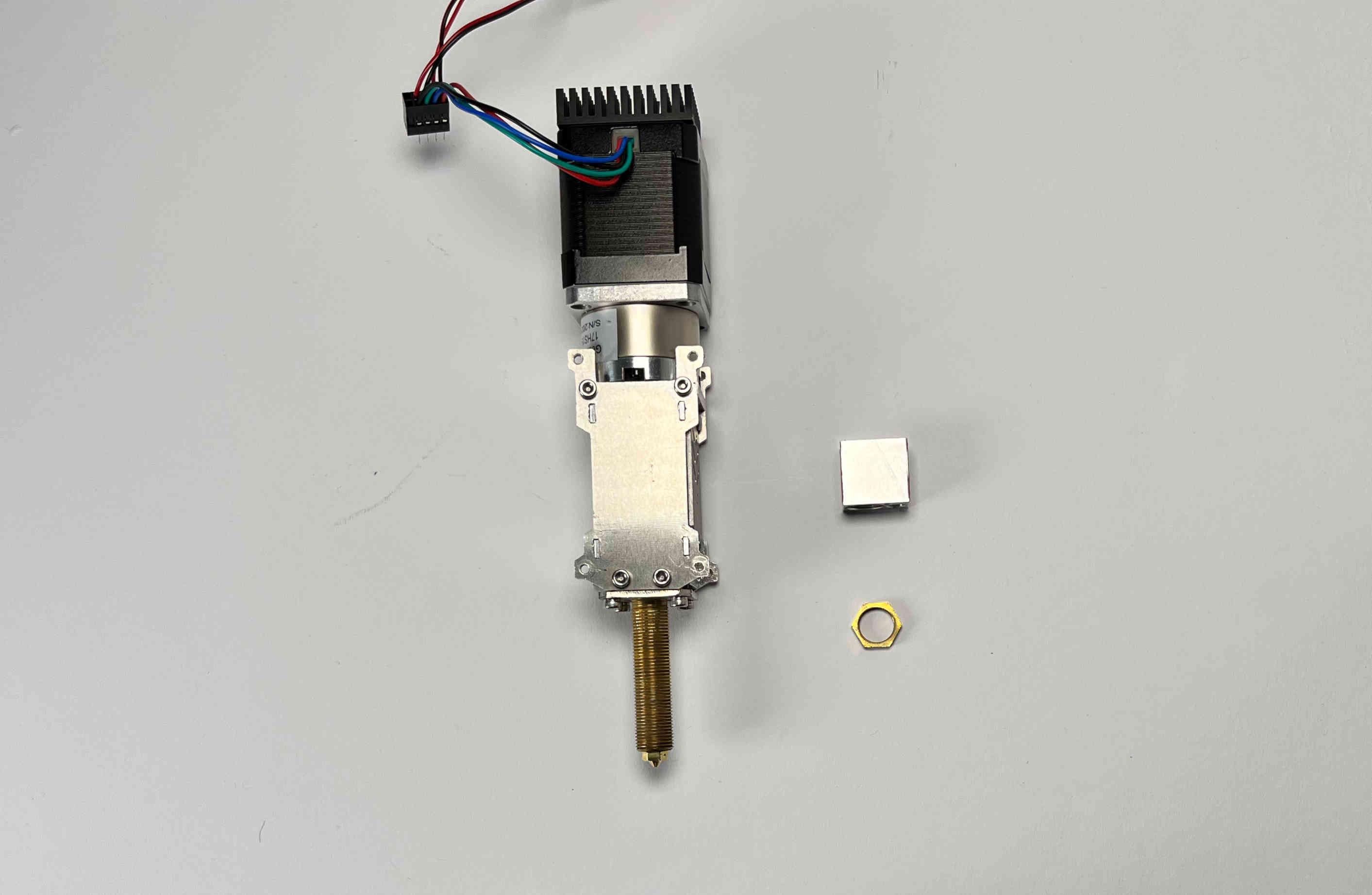
Remove the hex nut and the heater block from the hot end
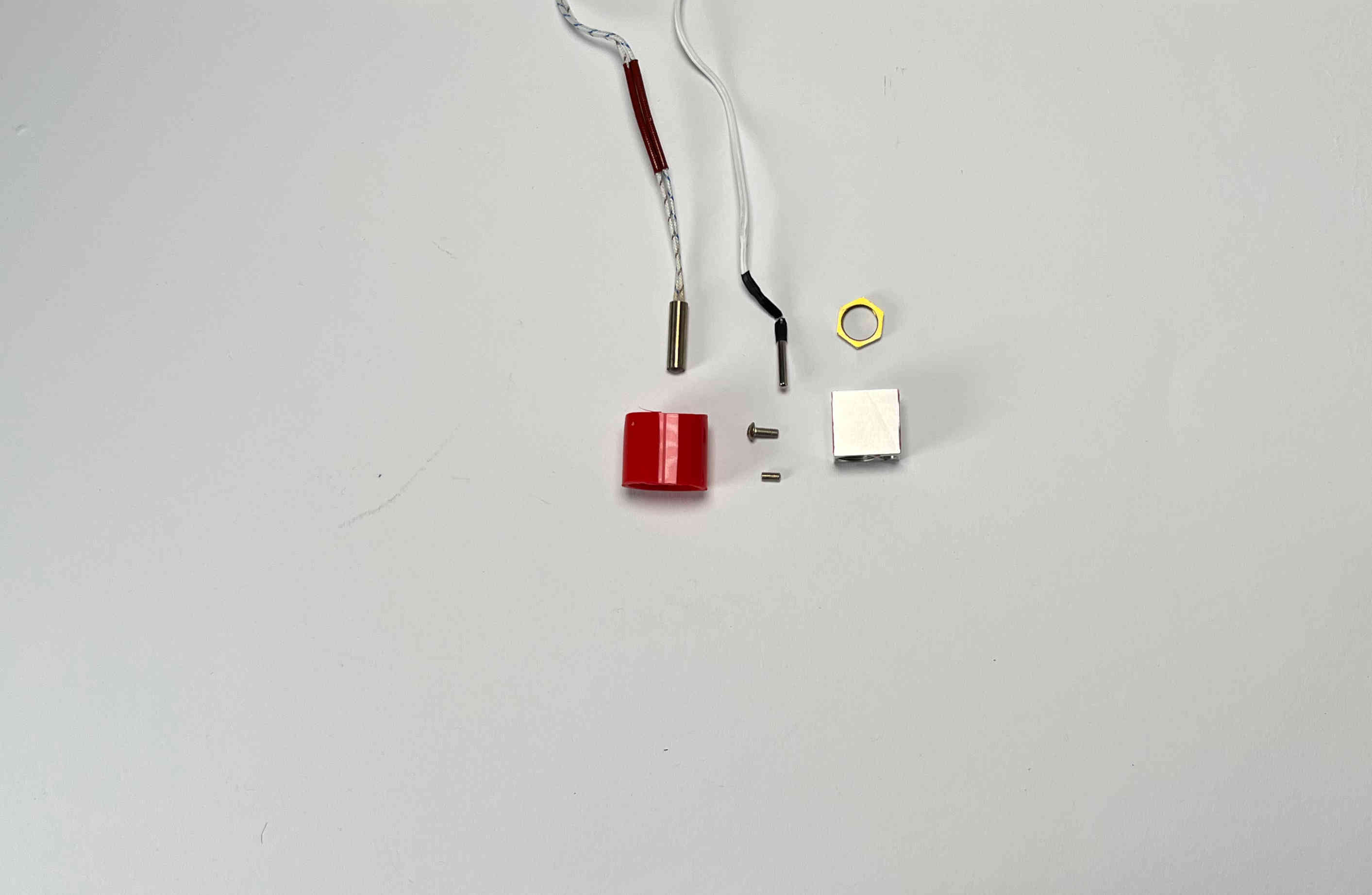
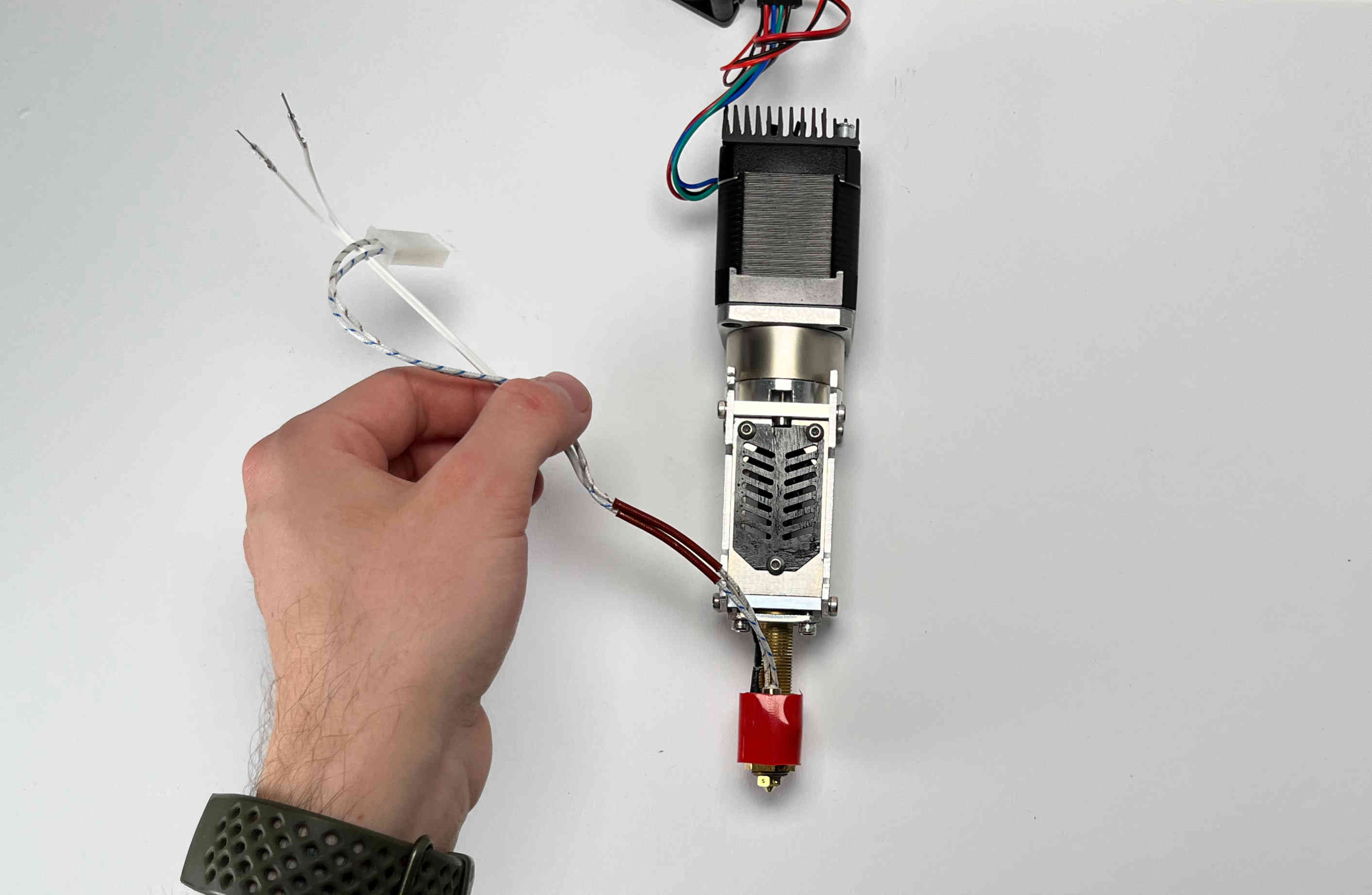
Prepare the heat cartridge, the thermistor and the silicone tube
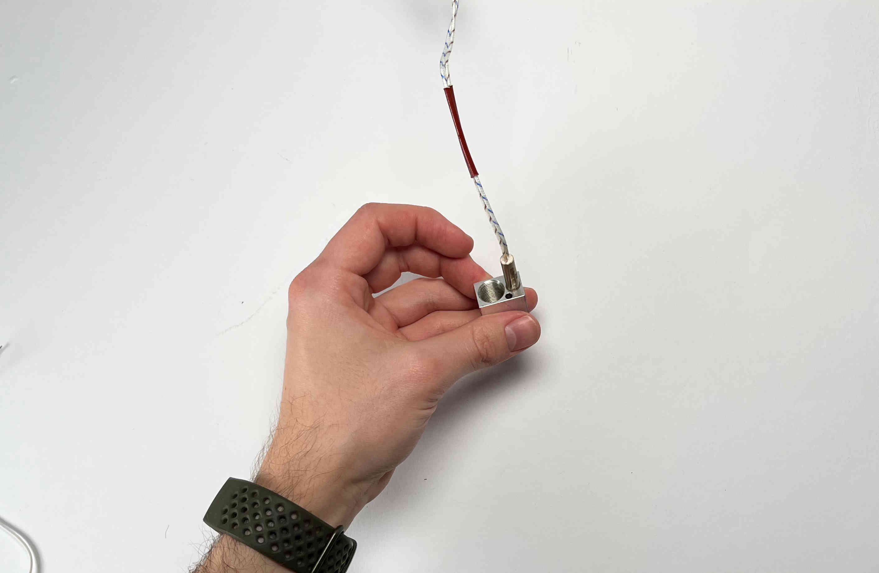
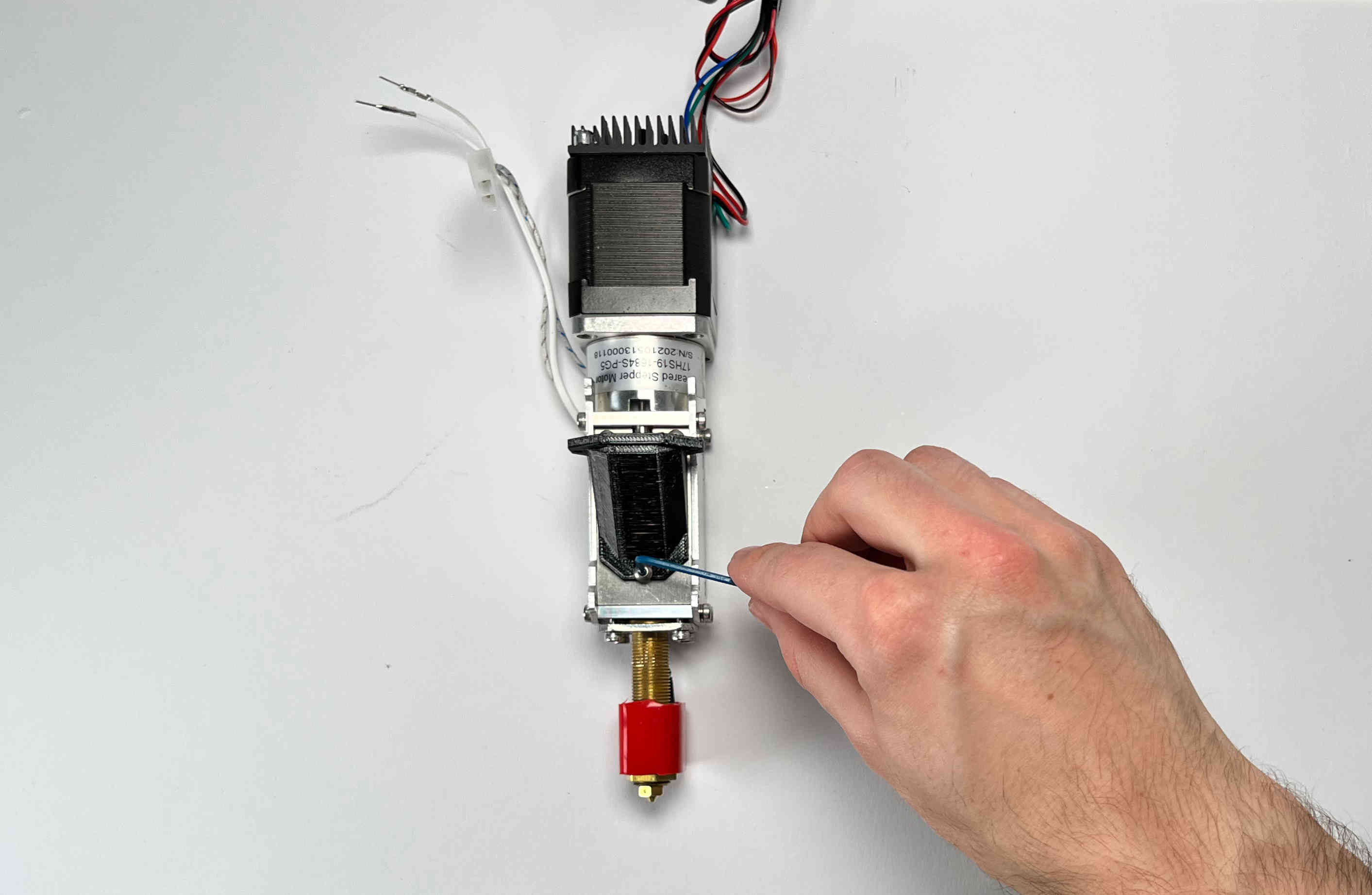
Insert the heat cartridge
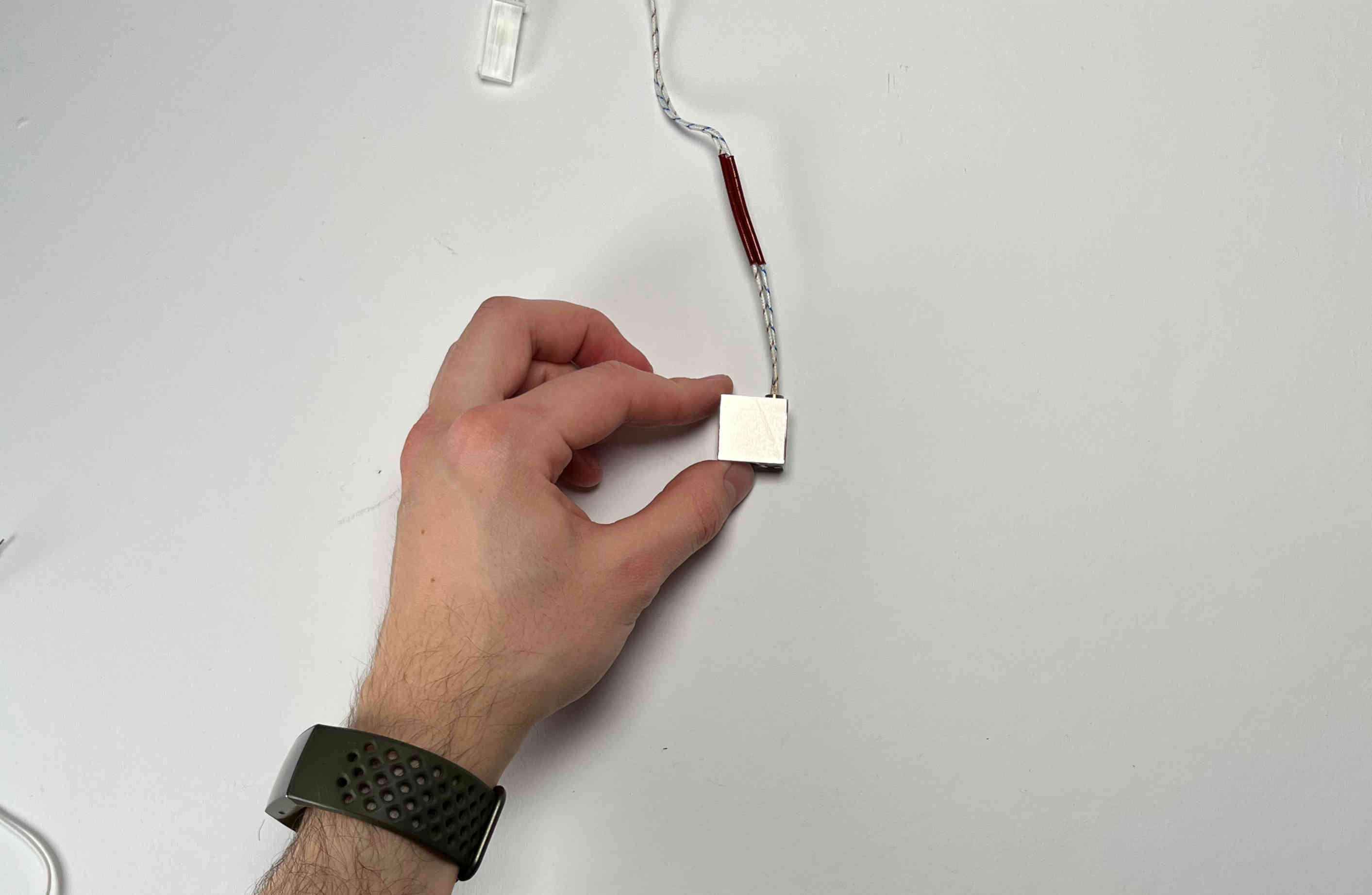
Make sure the heat cartridge is flush with the bottom of the heater block.
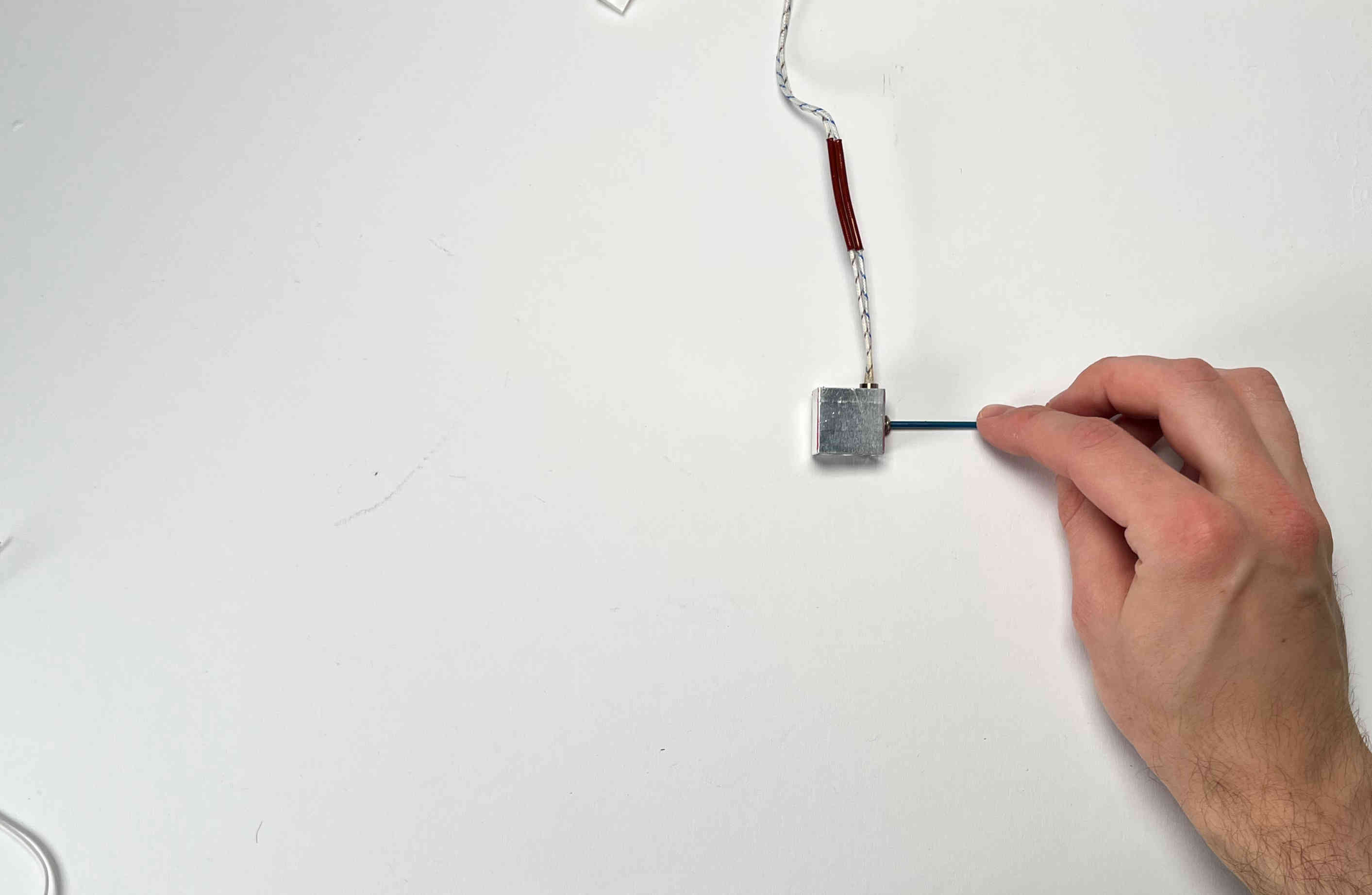
Carefully clamp the heat cartridge using the provided screw.
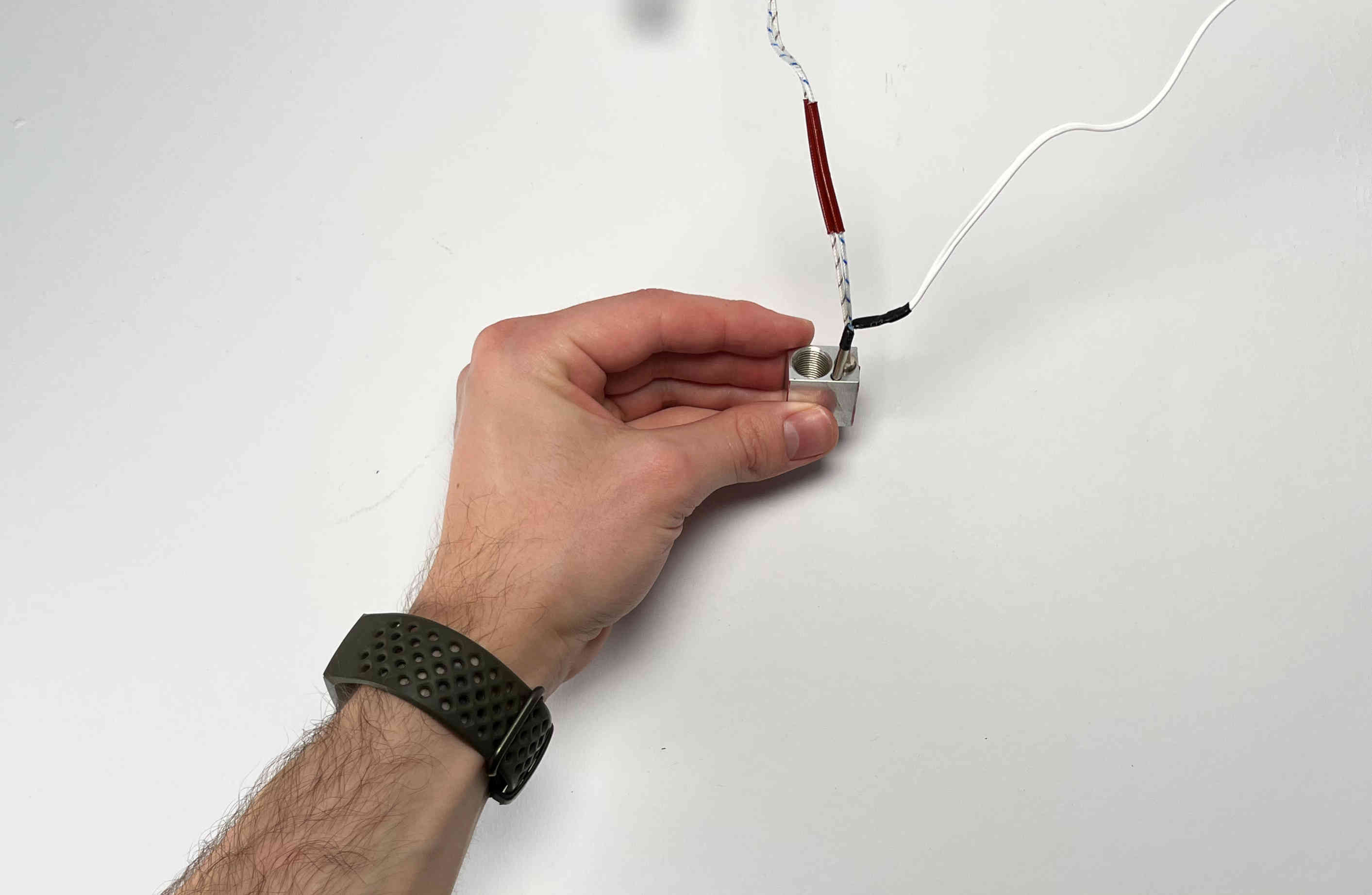
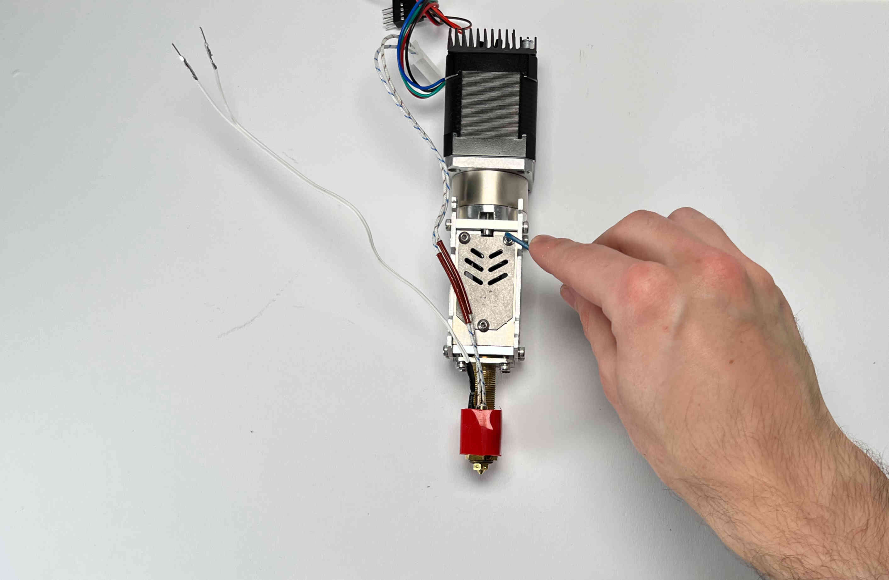
Insert the thermistor (It makes sense to check the thermistor by mearing its resistance. It should be around 100 kOhm)
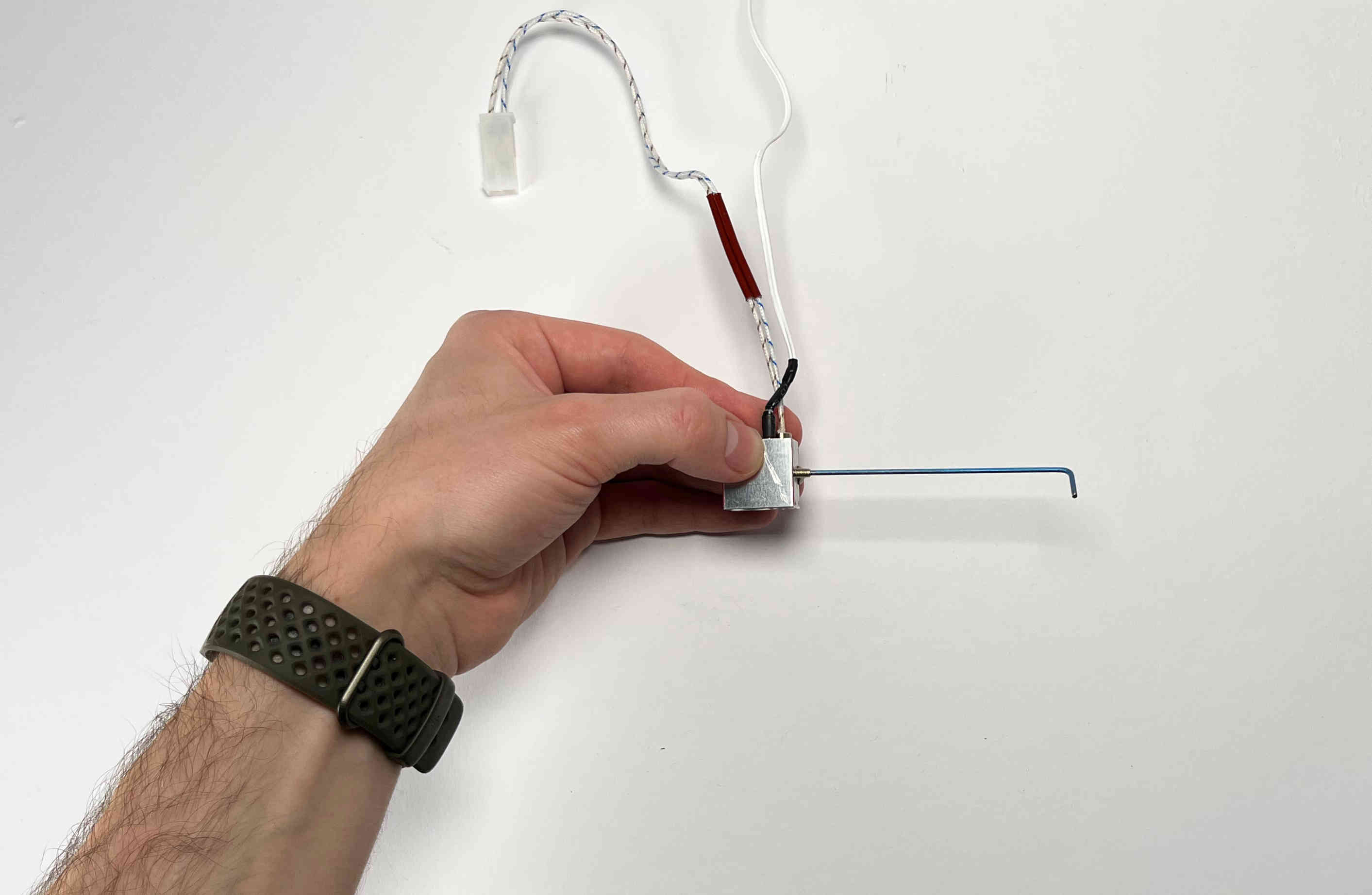
Carefully clamp the thermistor using the provided set screw.
Cover the heater block with the silicone tube.
Make sure the silicone sock is flush with the lower side of the heater block.
Carefully reinstall the heater block on the Pellet Extruder.
Tighten the heater block in place with the hex nut.
Pellet Parking Spot
Prepare the printed part “pellet_parking”, the machined part “pellet_bracket”, two M3 locking nuts, one M3x5 screw, two pins, the small magnet, and two M3x16 screws (The last three items are included in the “blank toolplate and dock” kit from E3D).
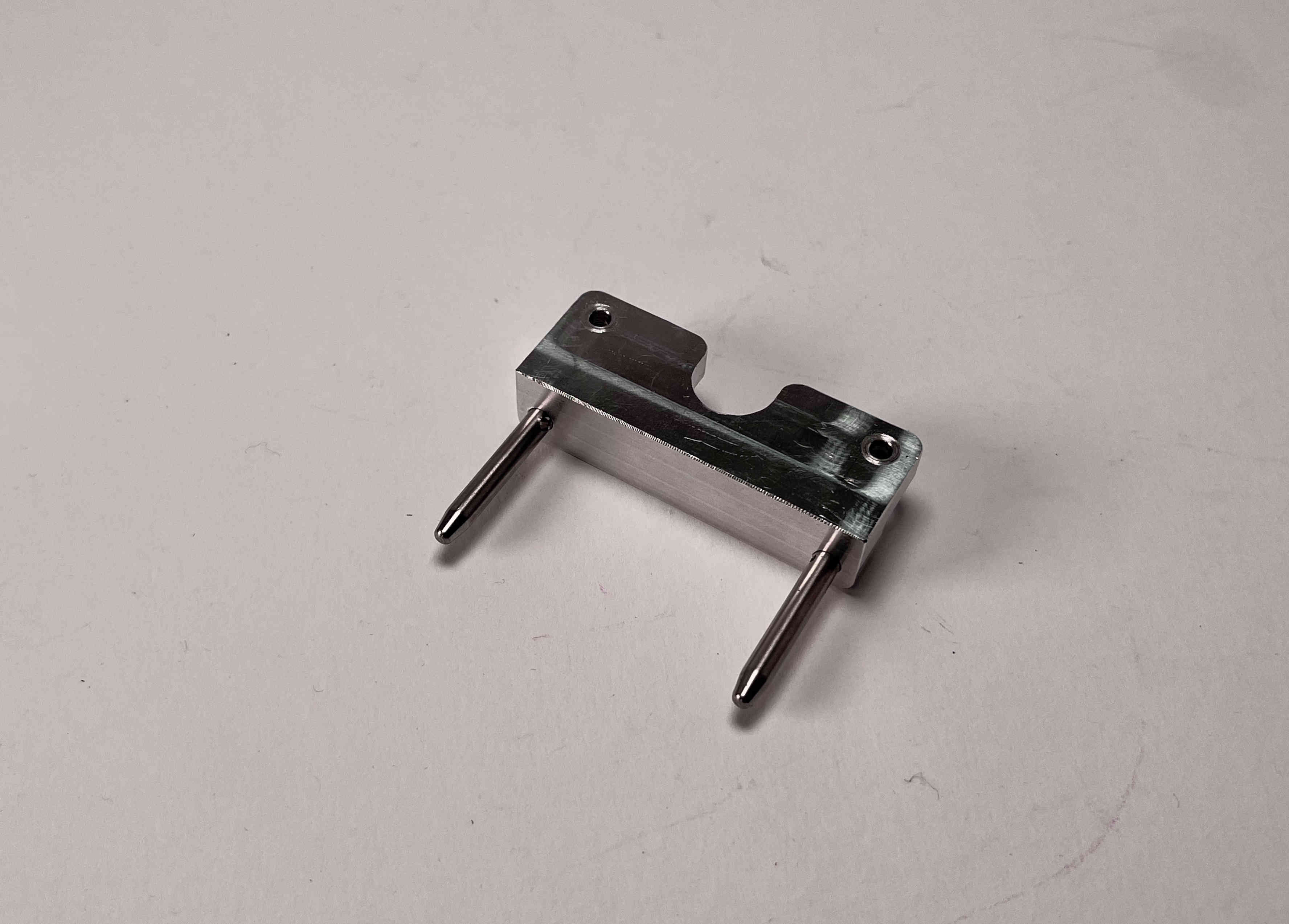
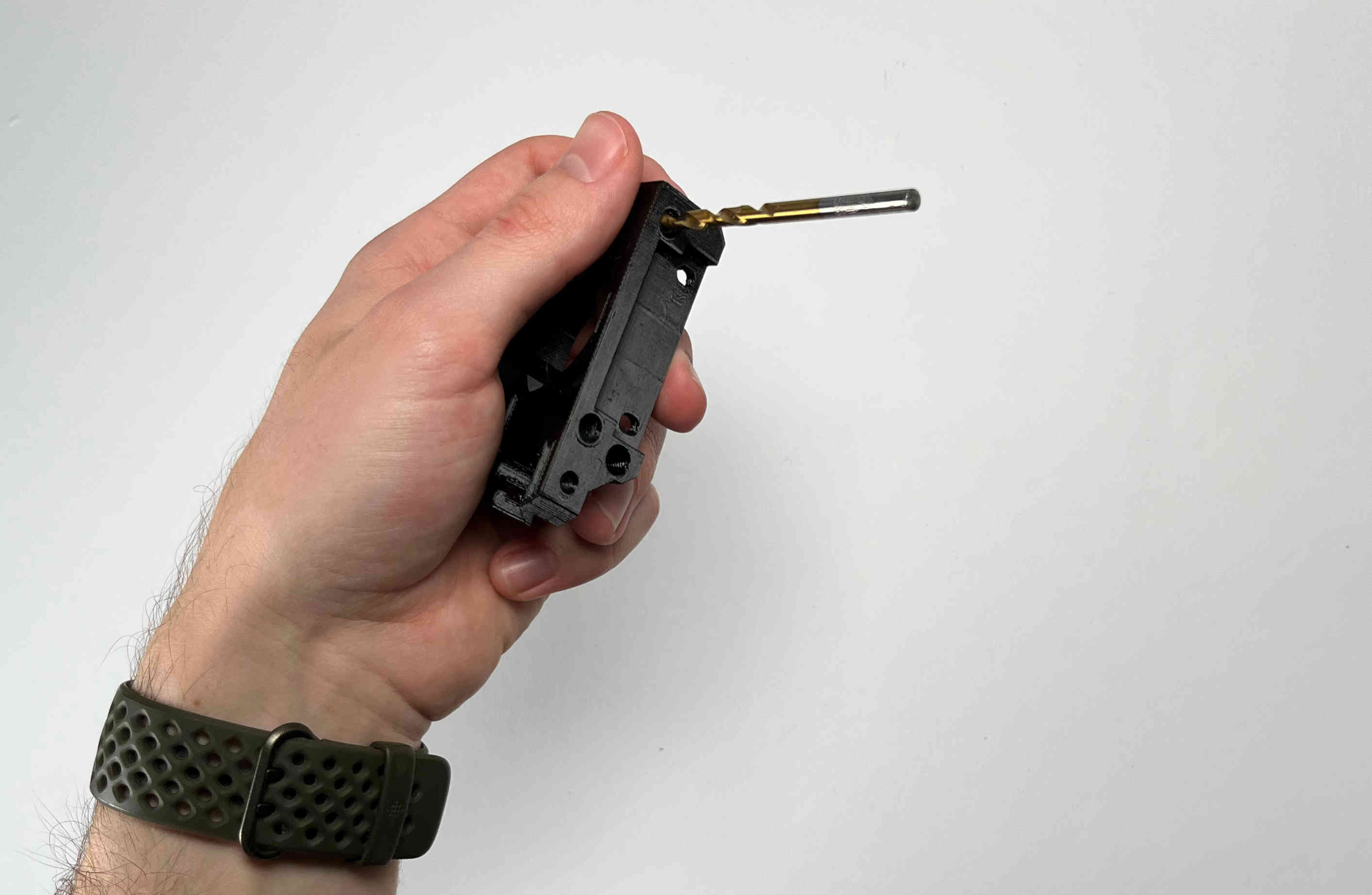
Screw the two pins into the pellet_bracket. If the fit is too tight carefully loosen up the outer hole with a 4mm drill bit.
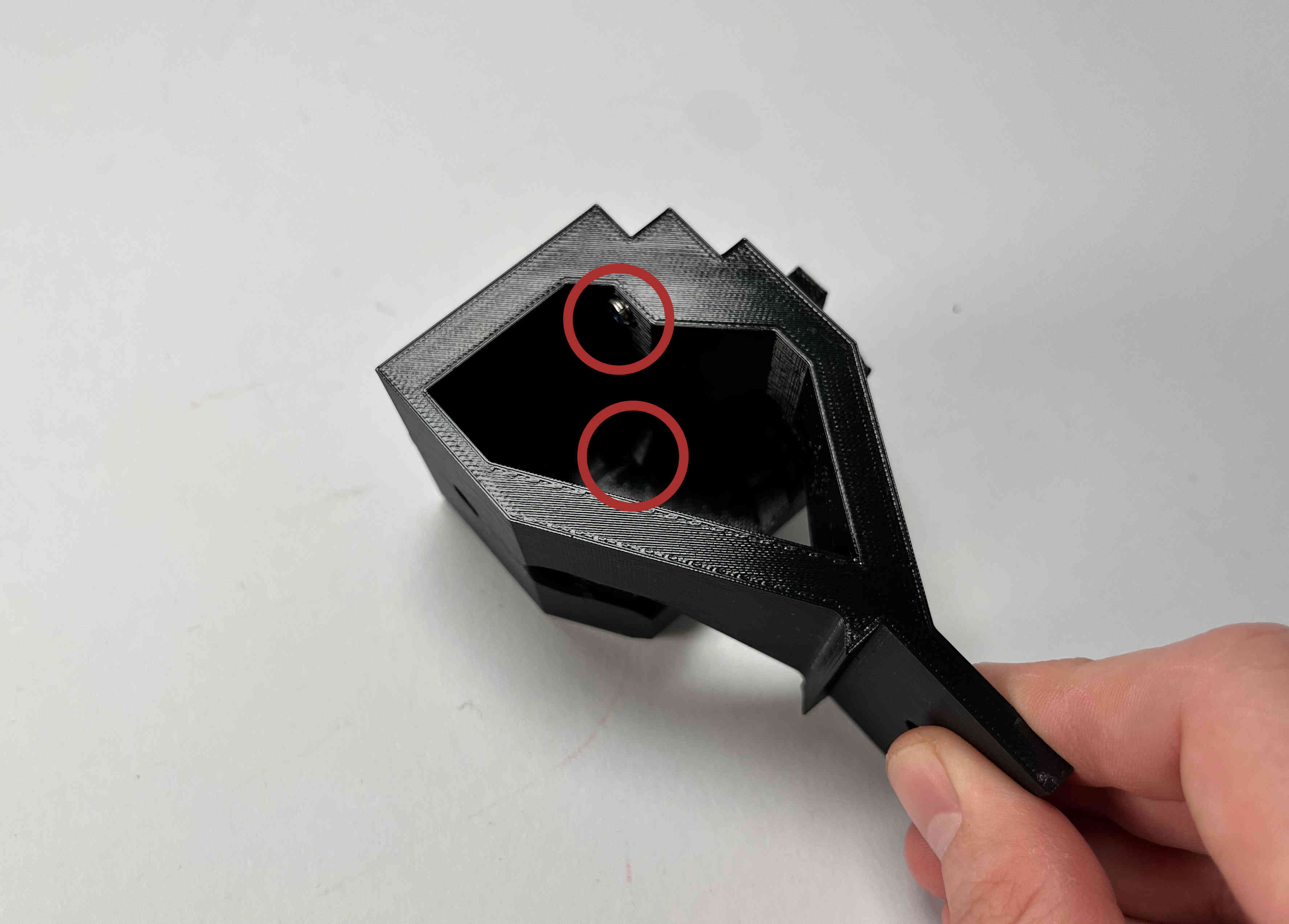
Insert two M3 locking nuts into the pellet_parking part
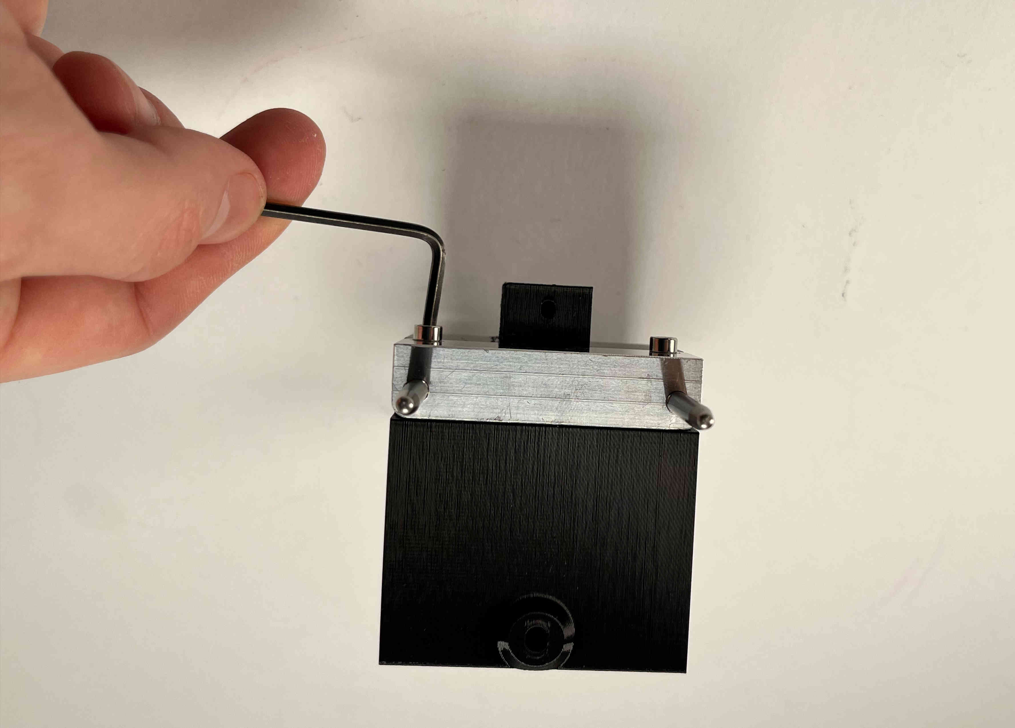
Tighten the bracket to the parking spot using the two M3x16 screws.
Carefully tap an M3 thread into the plastic part using the M3x5 screw. This is later used to clamp the cable brace.
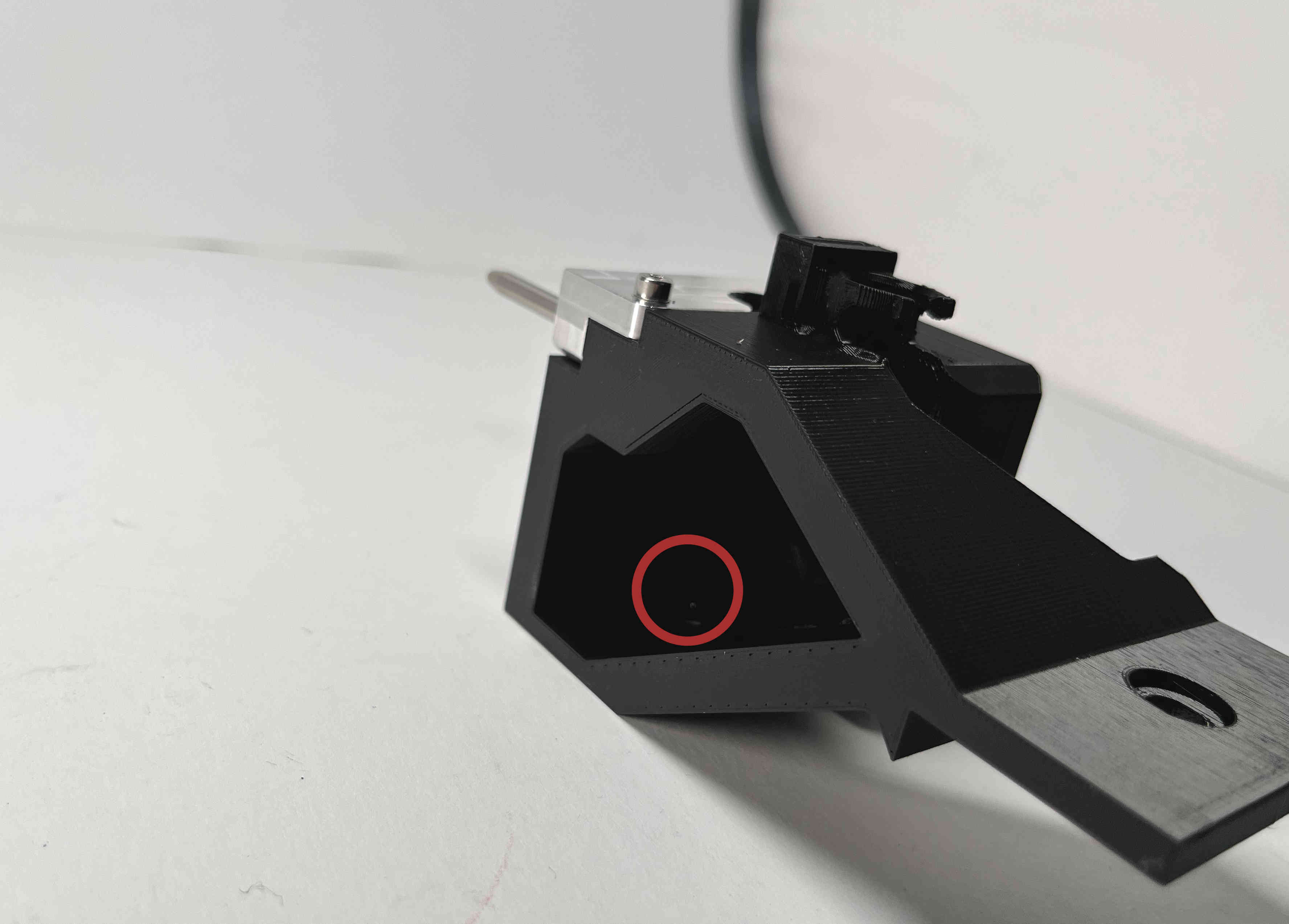
Push in the magnet until it is up against the outer plastic holding it in place.
Receiving Bracket
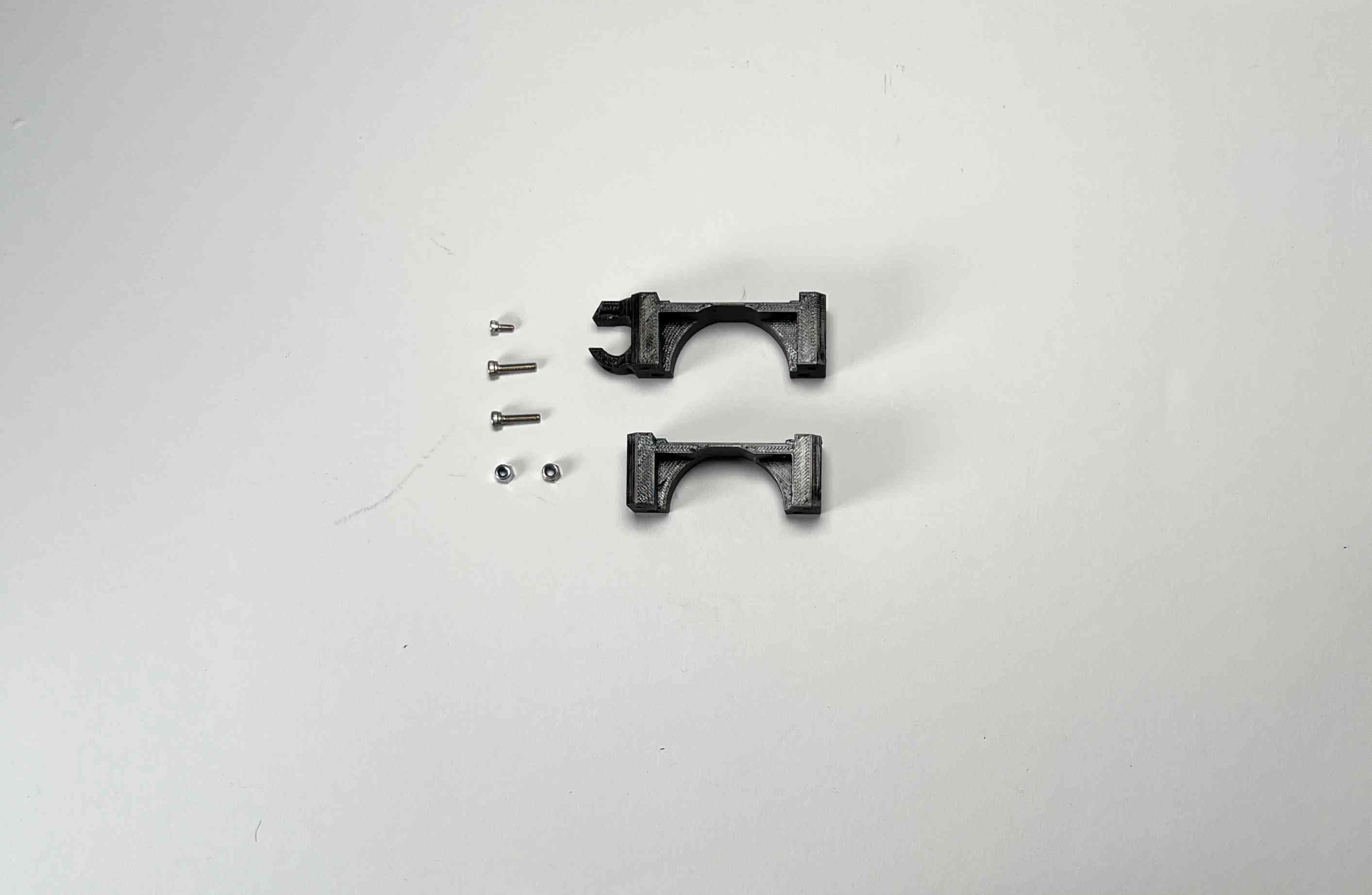
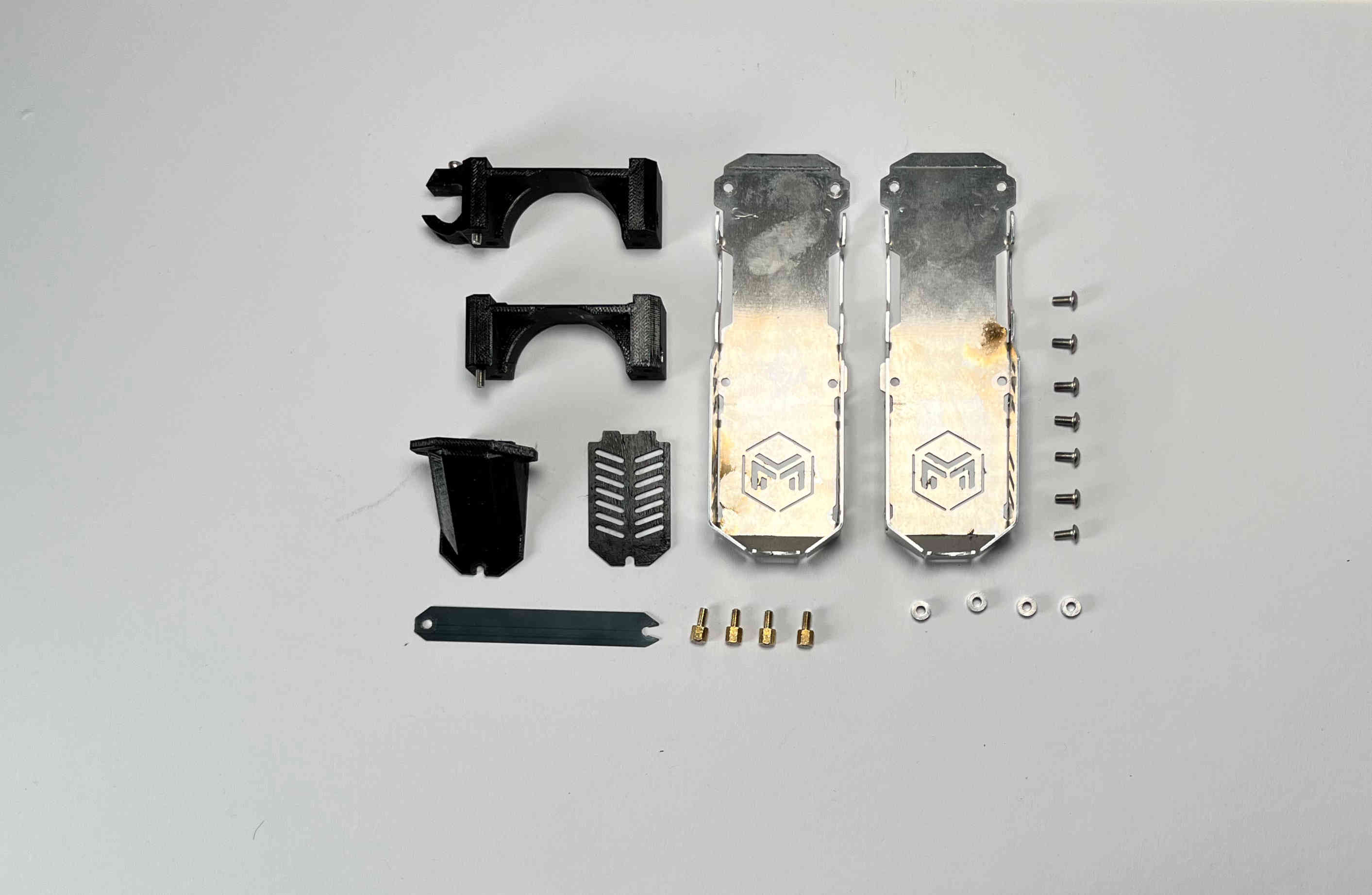
Prepare two M3 locking nuts, two M3x16 screws, one M3x5 screw, and the two parts of the “pellet_receiver”.
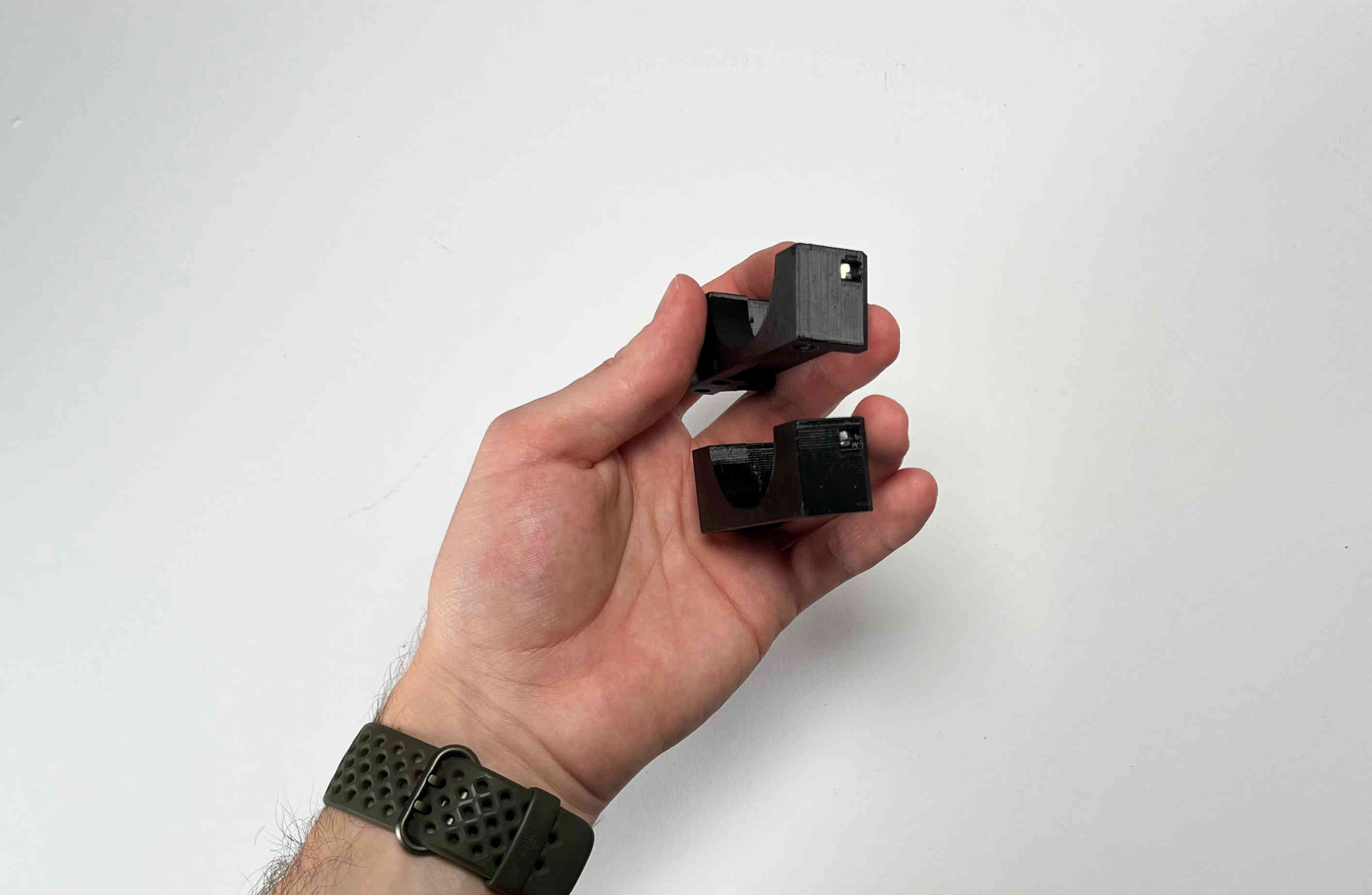
Insert one M3 locking nut into each of the two pieces of the “pellet_receiver” part.
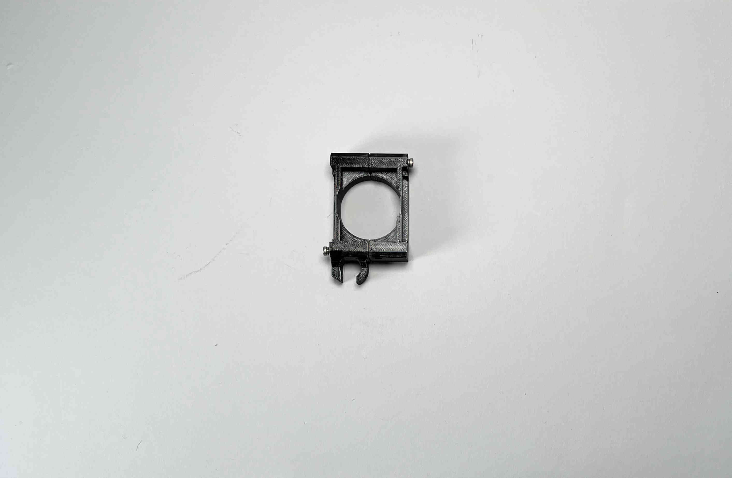
Place both parts upside down on a flat surface and join them using two M3x16 screws
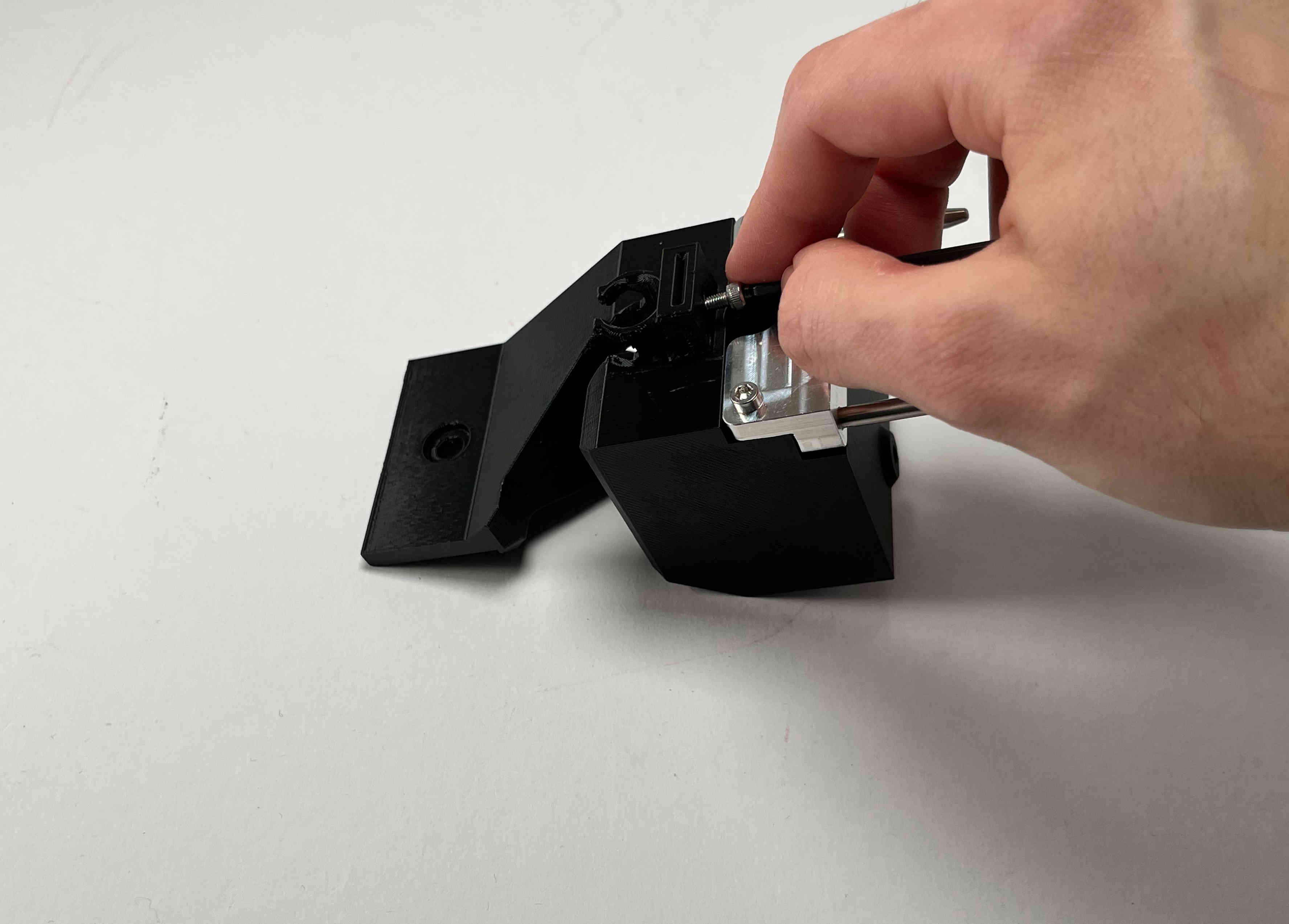
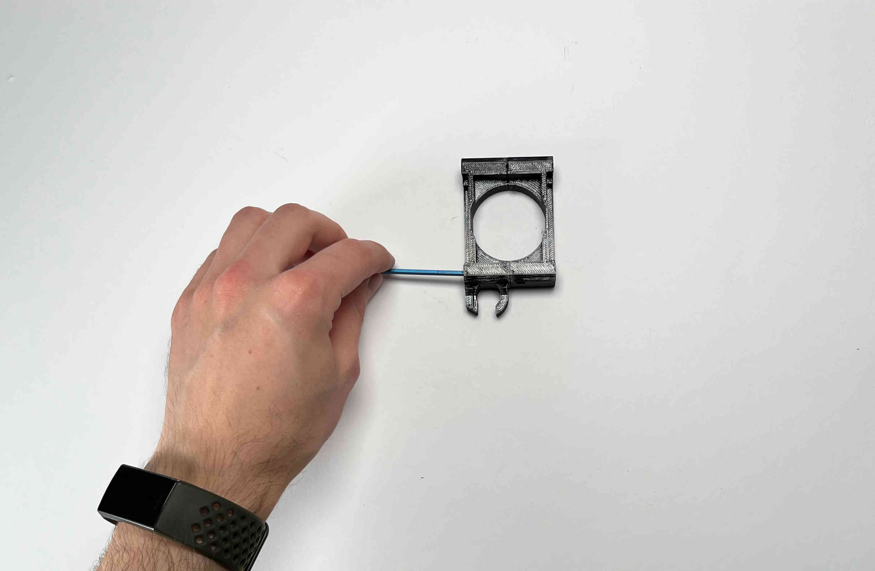
Using a 4mm drill bit carefully widen the receiver holes for the pins. Constantly check the fit using the already assembled parking spot
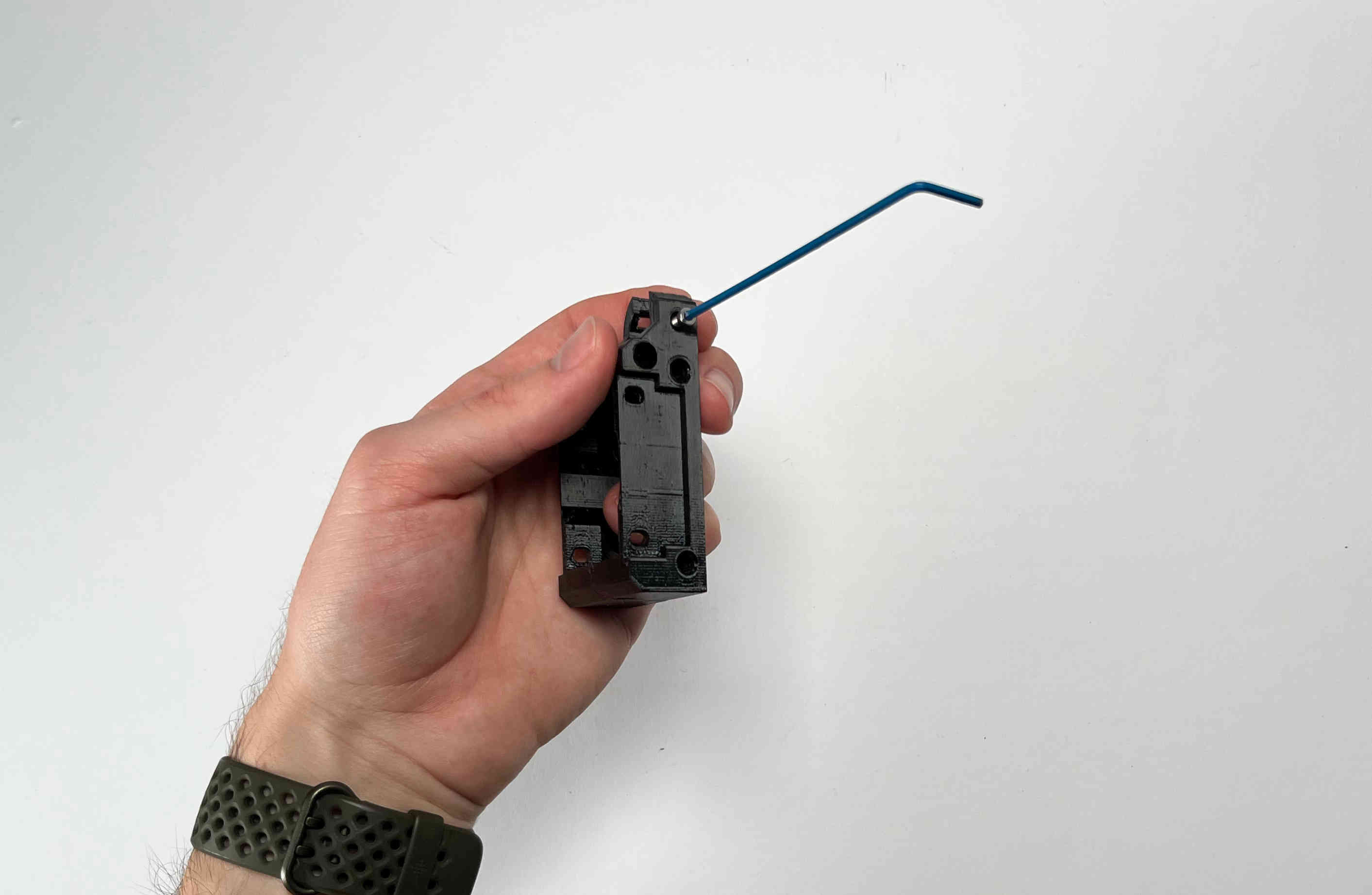
Carefully tap an M3 thread into the plastic part using the M3x5 screw. This will later be used to clamp the cable brace.
Unscrew the two parts and set them aside for future steps.
Body Assembly
Prepare the two parts of the “pellet_receiver”, the “pellet_fan_grate”, the “pellet_guide”, the cut and predrilled steel strip, and the two outer aluminium brackets of the pellet head including the screws, that held it down.
Remove the aluminium grate from the pellet extruder.
Add the “pellet_fan_grate” using the screws you just removed.
On the other side insert two of the same kind of screws. Do not tighten them yet.
Align the “pellet_guide” using the two upper screws and fasten it down using all three screws.
Place the pellet extruder on its side, so the pellet guide is facing the right, and the heater cables are facing the left.
Place the “pellet_bracket_A” (the one with the cable brace) on the side of the extruder.
Place one of the outer aluminium brackets on top of the pellet_bracket_A.
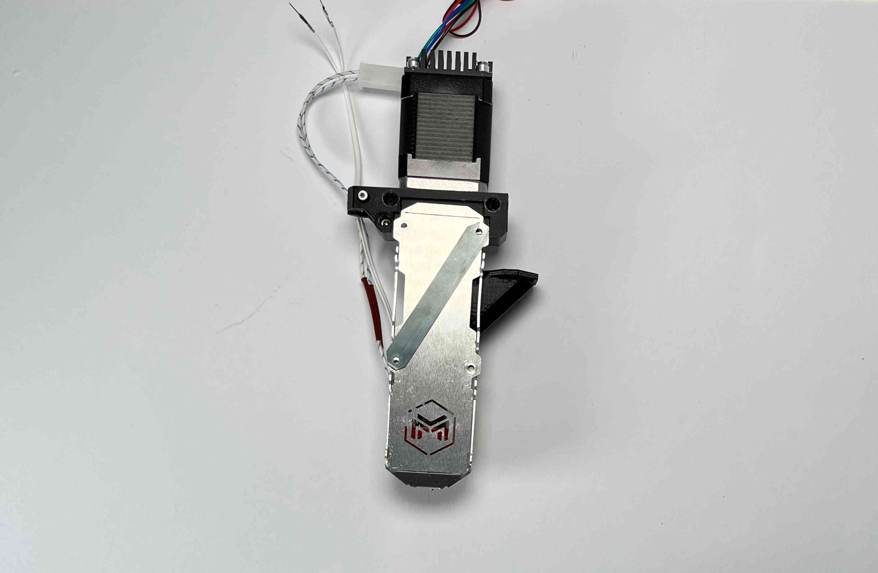
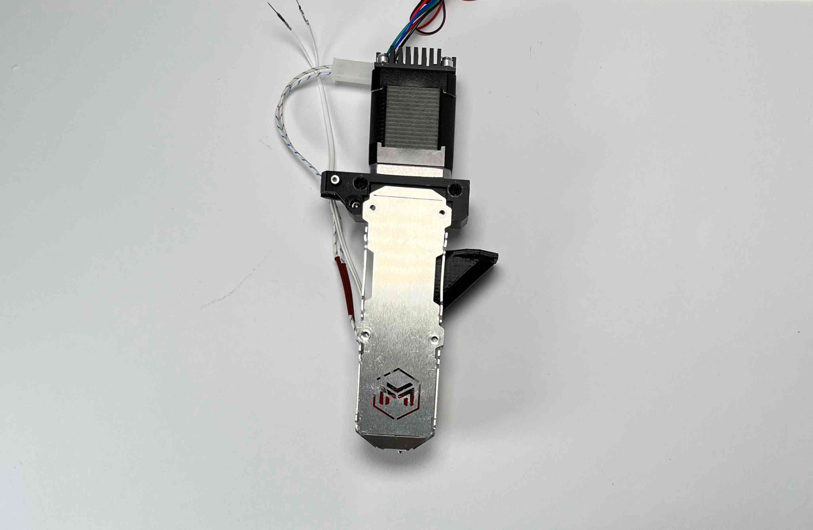
Place the steel strip on top of the aluminium bracket.
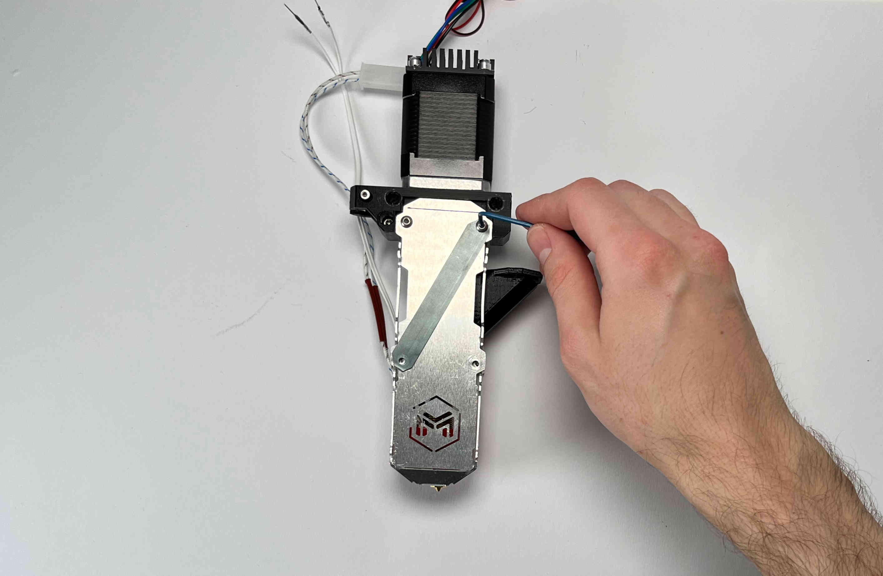
Insert the M3 screws. Do not tighten yet.
Insert two aluminium spacers and the other two M3 screws. Do not tighten yet.
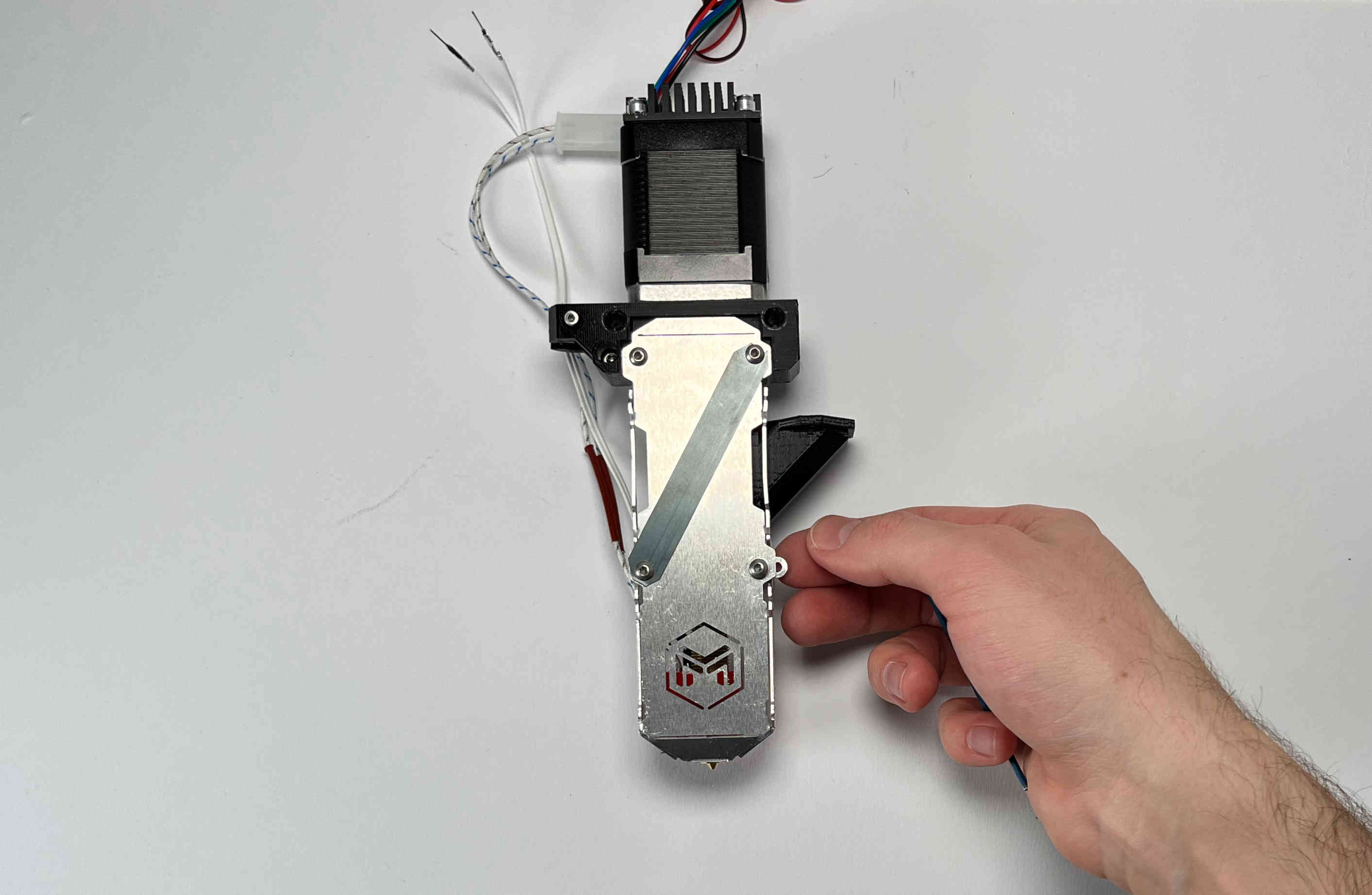
Push the pellet_bracket_A all the way up against the motor and tighten down the two upper M3 screws. This is essential for a good fit with the parking spot once installed on the printer.
Tighten the other two screws.
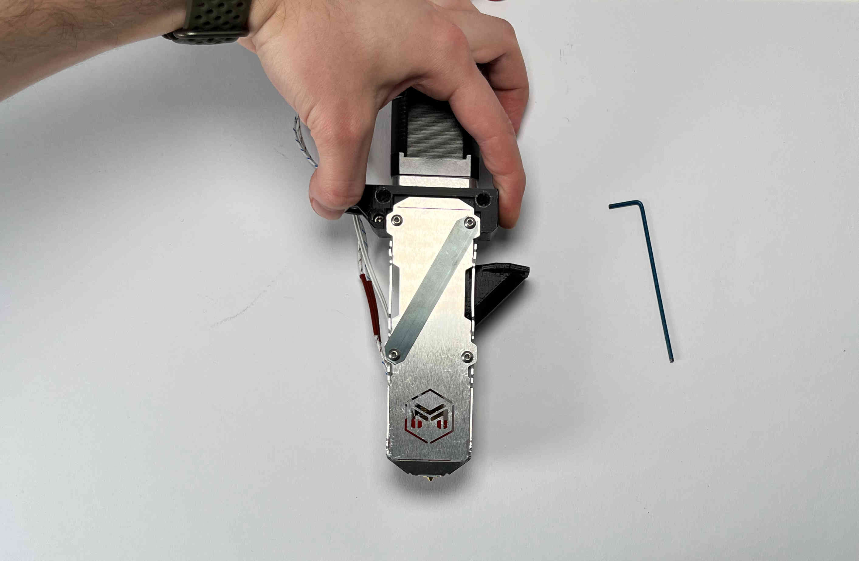
For future steps make sure the heater cables are tucked inside the aluminium bracket.

Turn the extruder around.
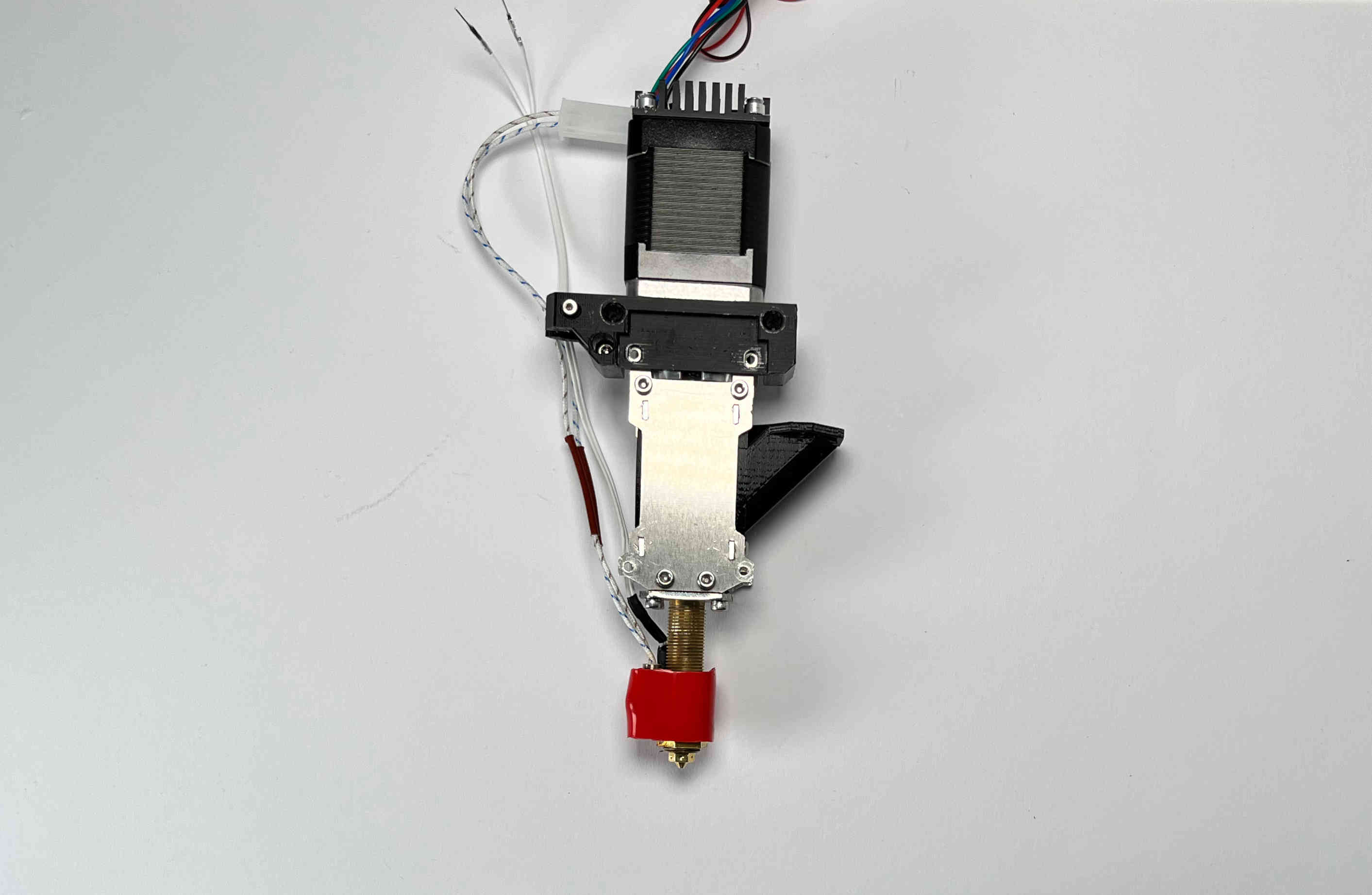
Place the “pellet_bracket_B” on the extruder.
Place the other outer aluminium brackets on top of the pellet_bracket_B. Make sure the heater cables are still guided inside the lower part of the aluminium bracket.
Insert the M3 standoffs. Do not tighten yet.
Insert two aluminium spacers and the other two M3 standoffs. Do not tighten yet.
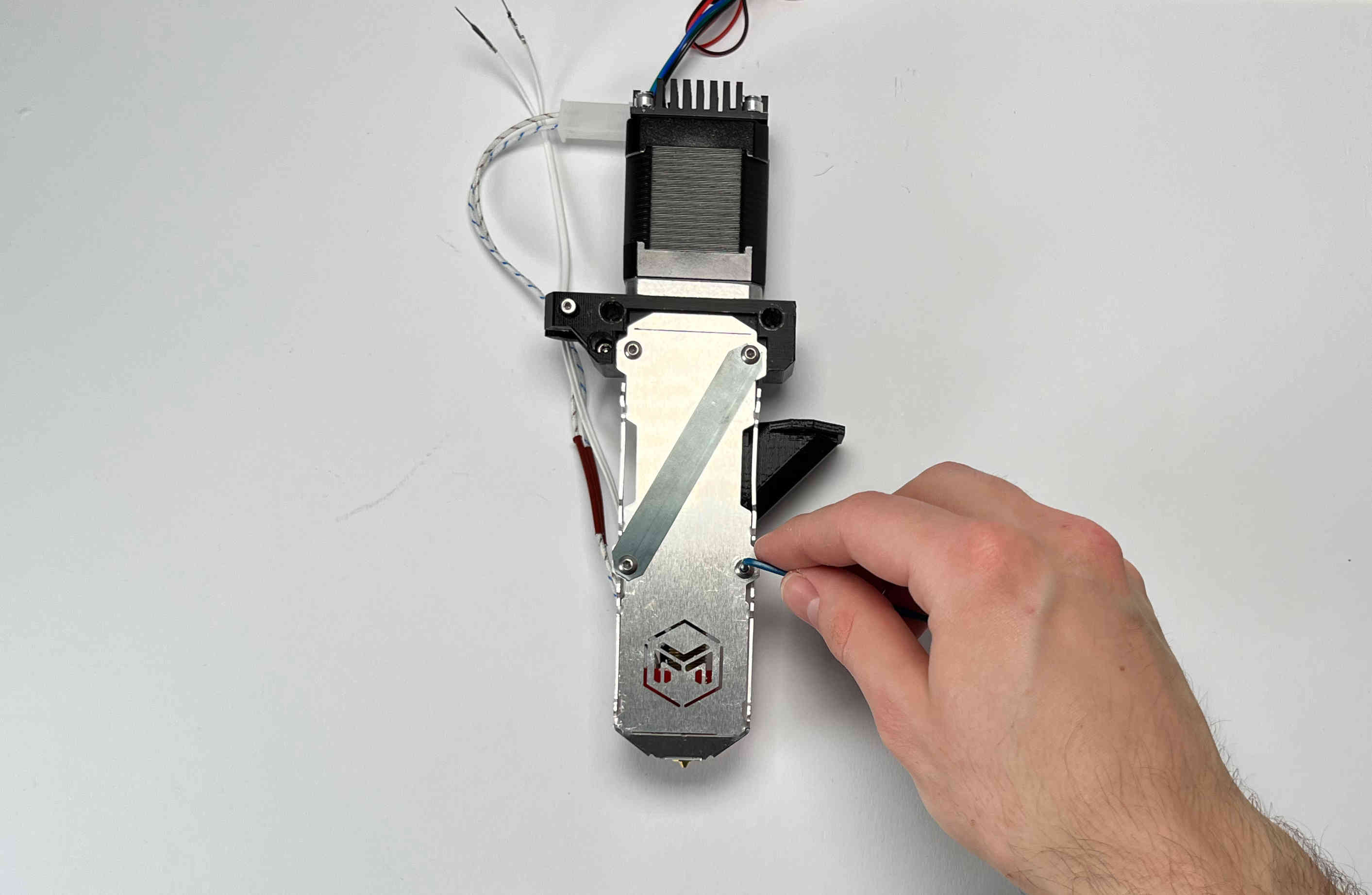
Push the pellet_bracket_B all the way up against the motor and tighten down the two upper M3 standoffs.
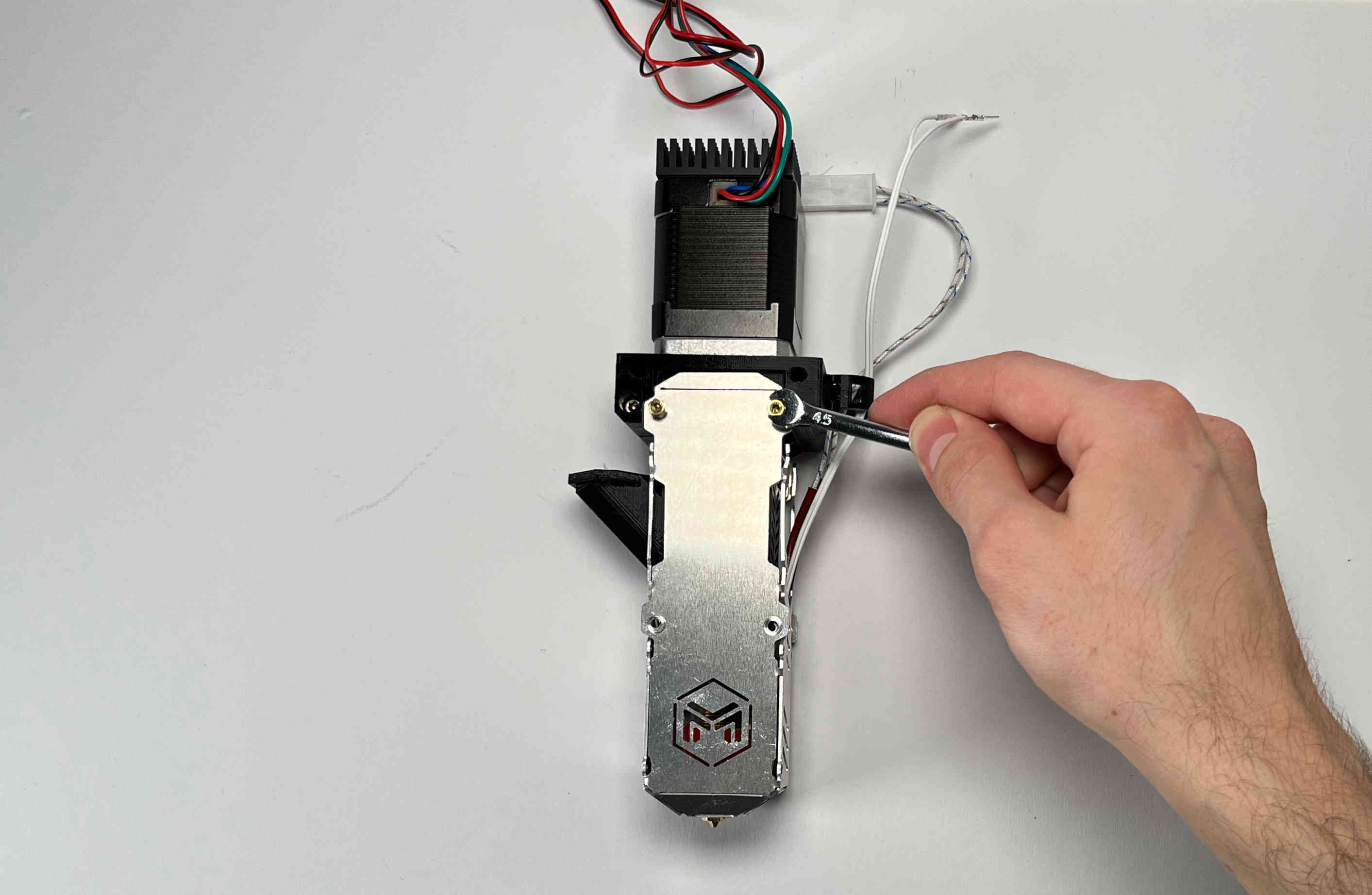
Tighten the other two standoffs. (TIP: if you don’t have a wrench handy, insert a short M3 screw into the standoffs and use it to tighten them down.)
Tighten the two M3 screws inside the pellet bracket.
Note: there should be no gap between the motor and the bracket.
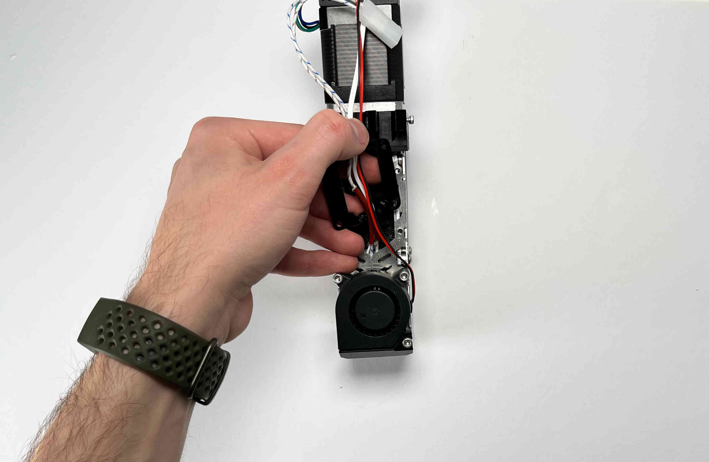
Fans
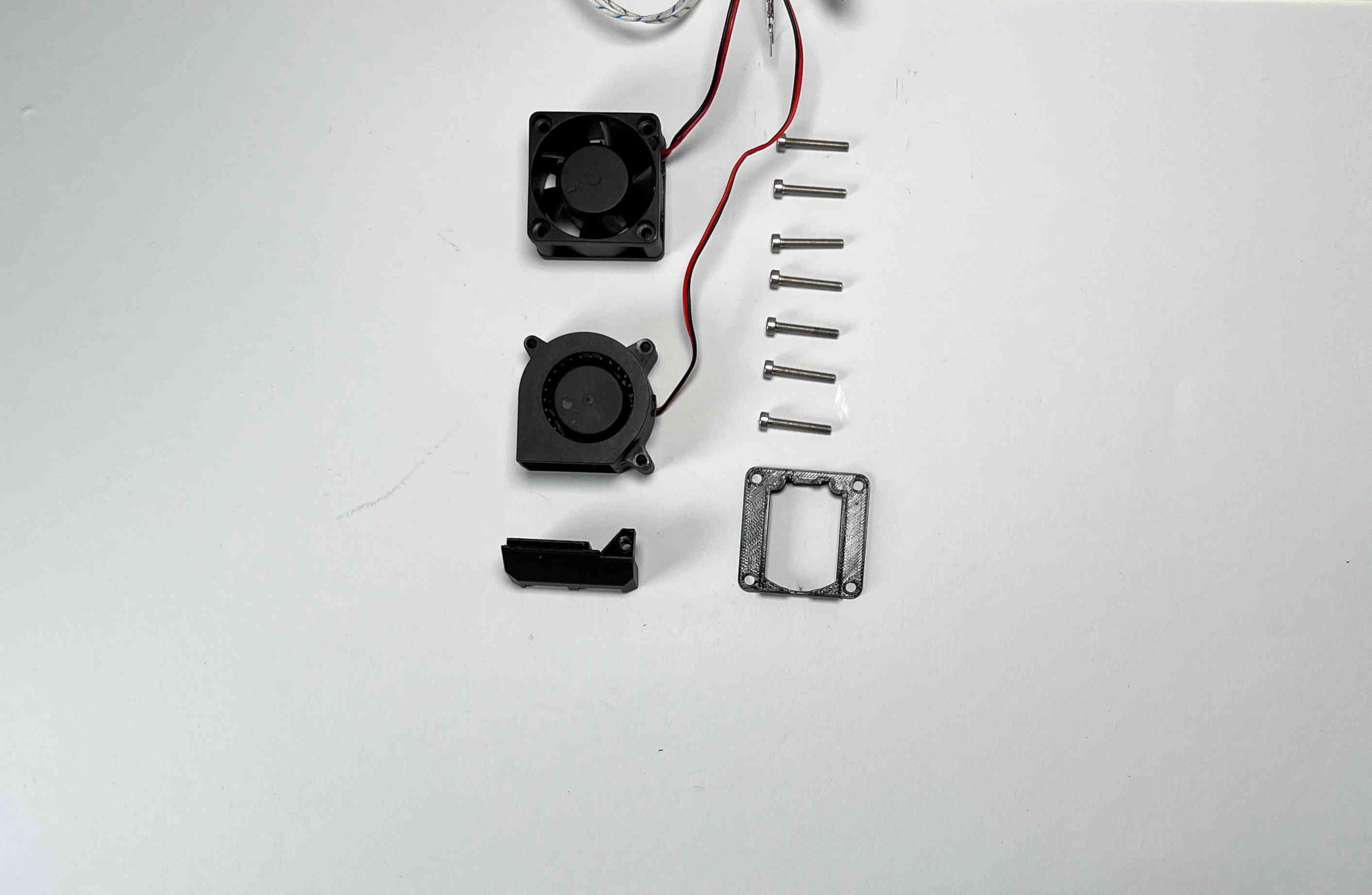
Prepare the “pellet_fan_shroud”, the “pellet_fan_guide”, the two fans, and the seven M3 screws that were holding down the fans.
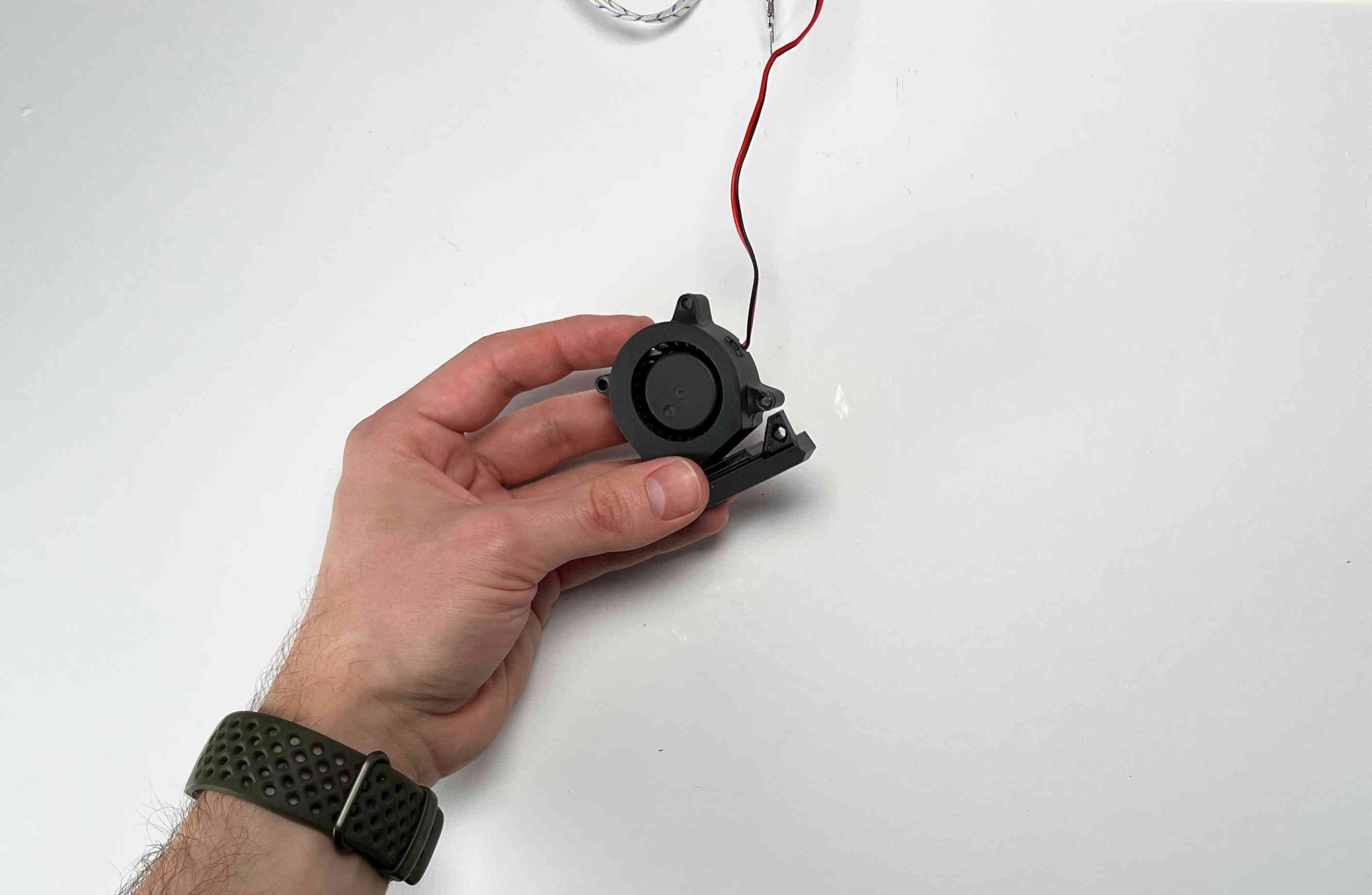
Insert the “pellet_fan_shroud” into the turbo/print fan.
Fasten the print fan to the extruder using three M3 screws.
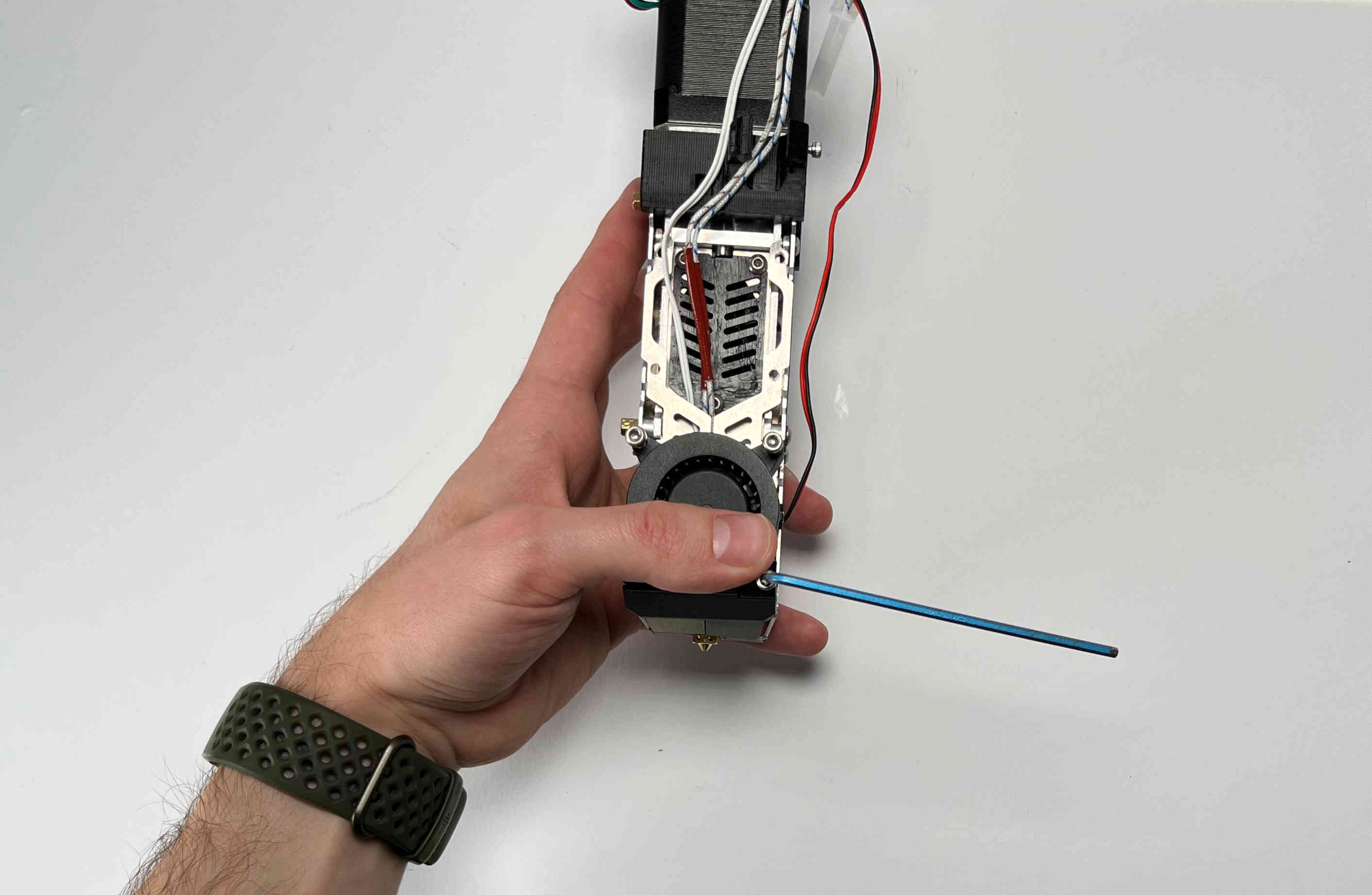
Take the “pellet_fan_guide” and rout the print fan cable and hot end cables through the notches.
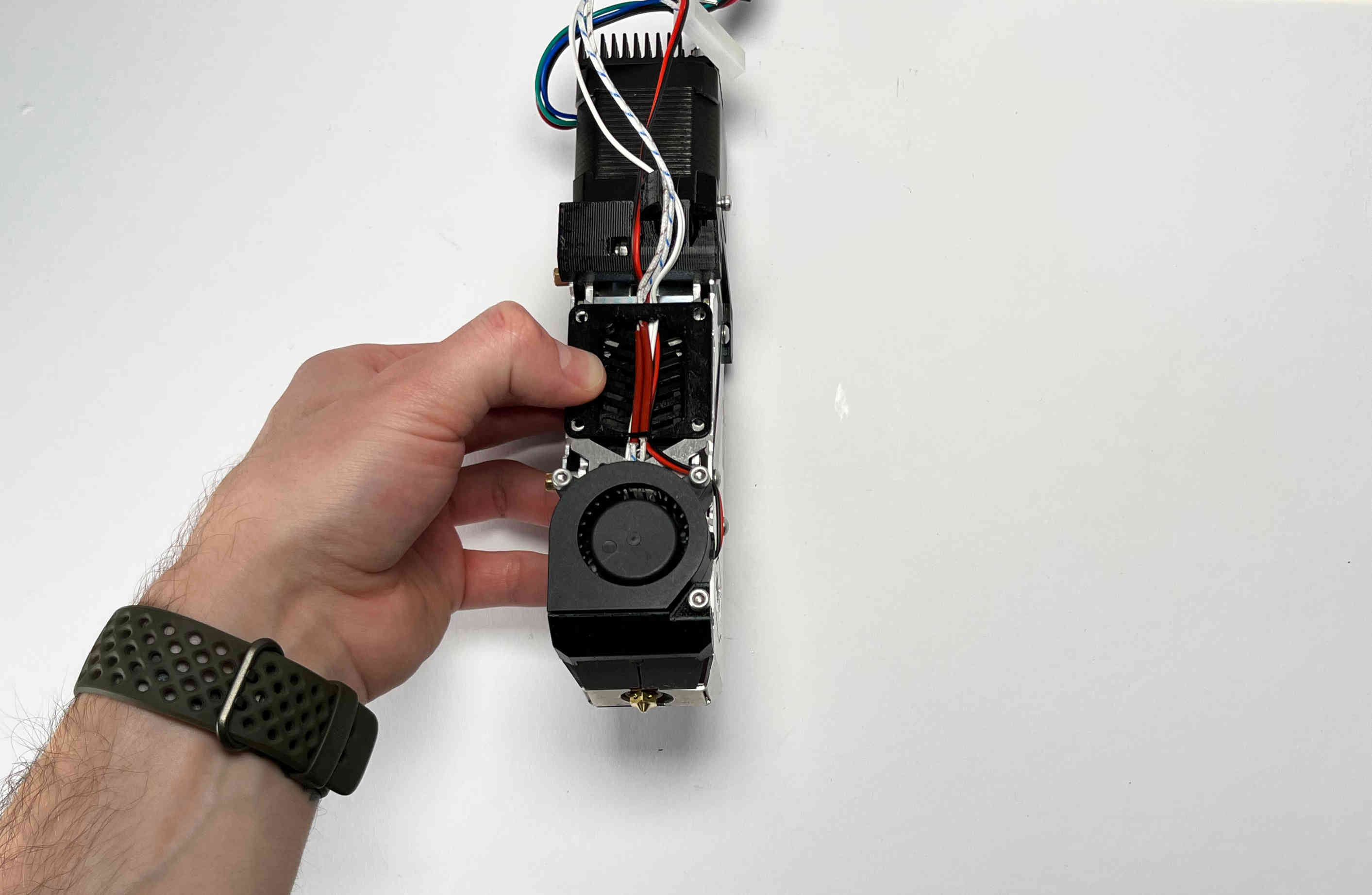
Place the fan guide on the extruder.
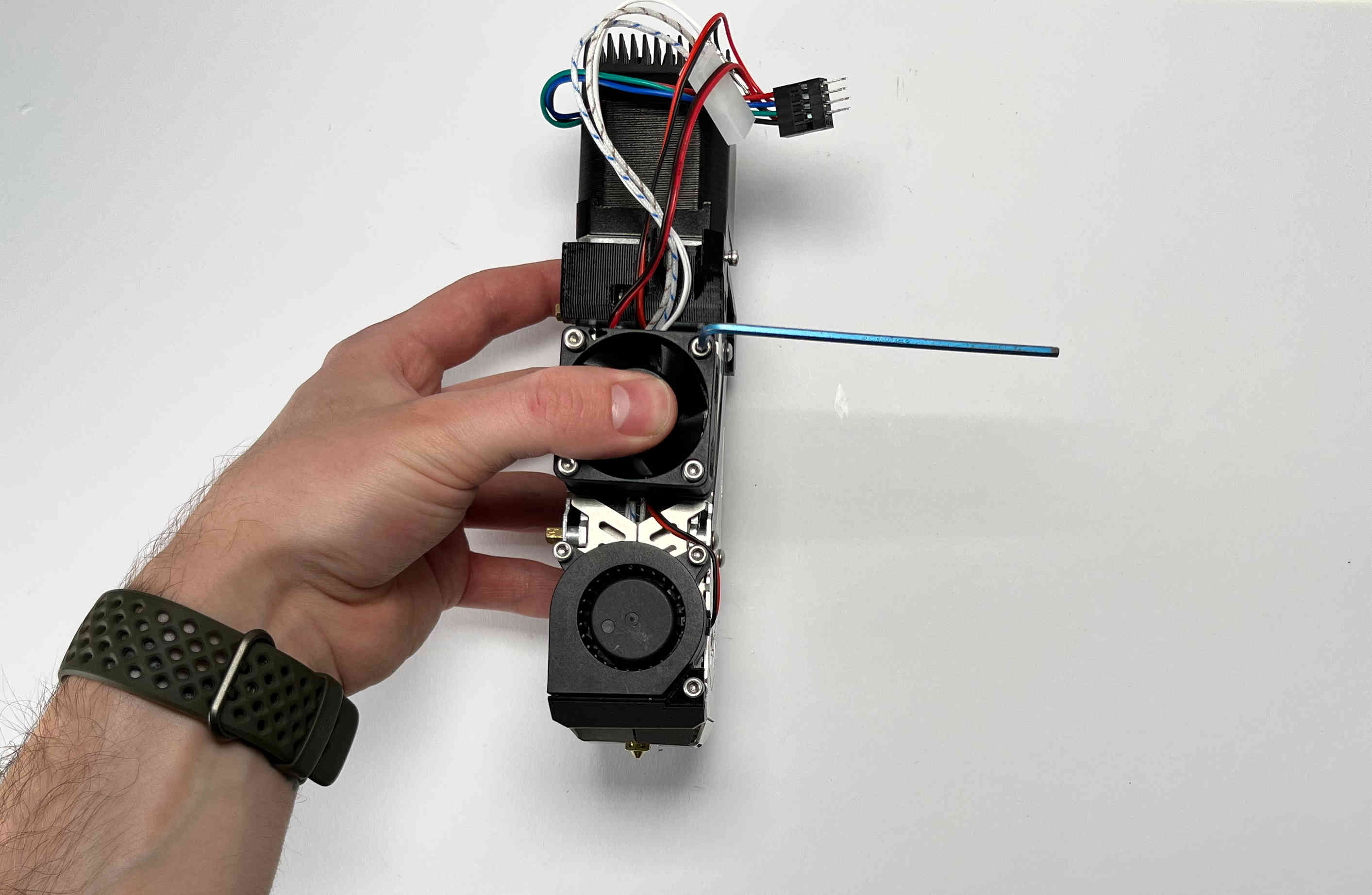
Place the fan on the fan guide making sure the cable is facing upwards and fasten using four M3 screws.
Receiver Plate
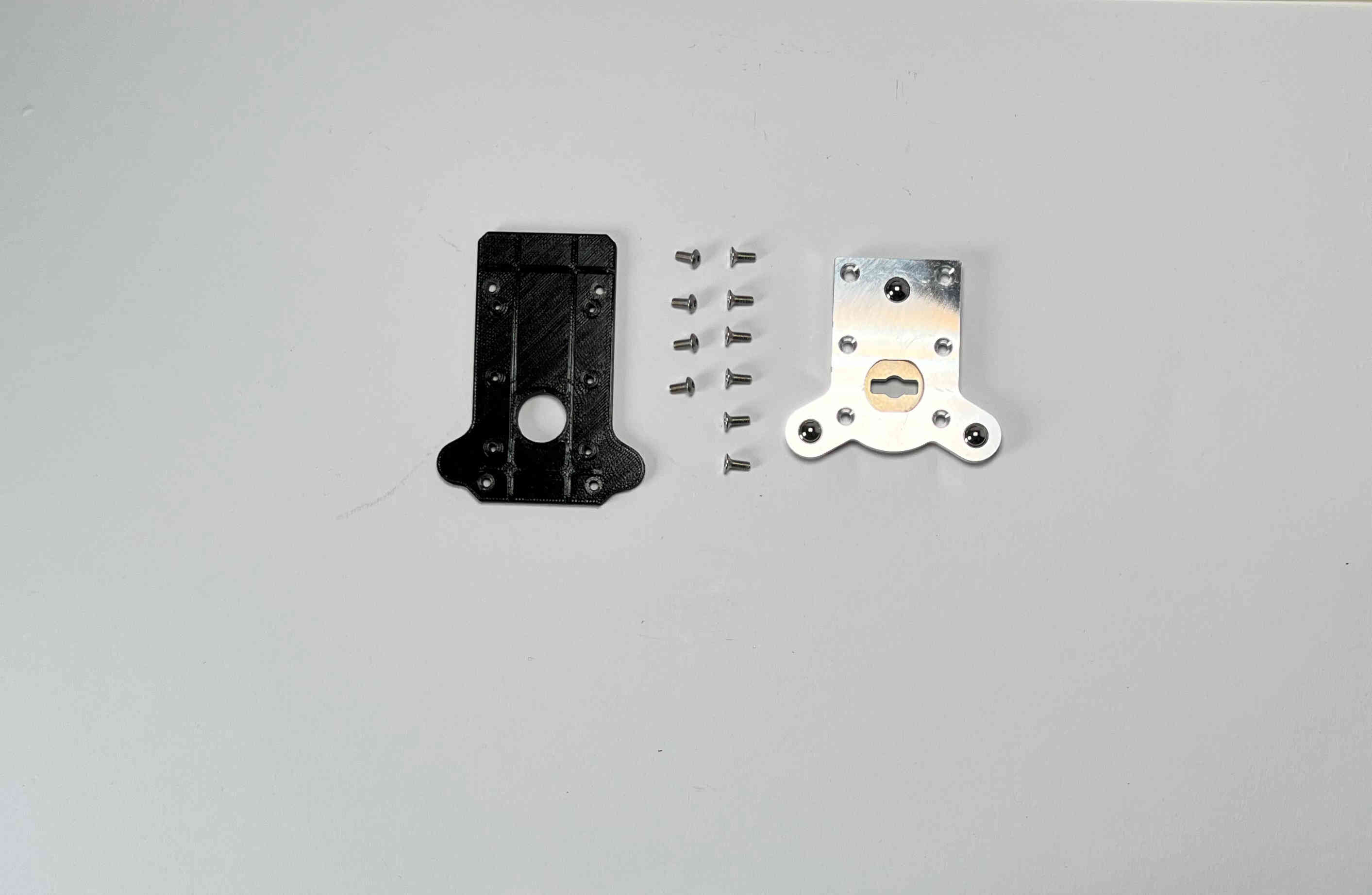
Prepare the “pellet_plate”, the M3 screws that were inserted into the standoffs, and the E3D Toolplate including its six countersunk mounting screws.
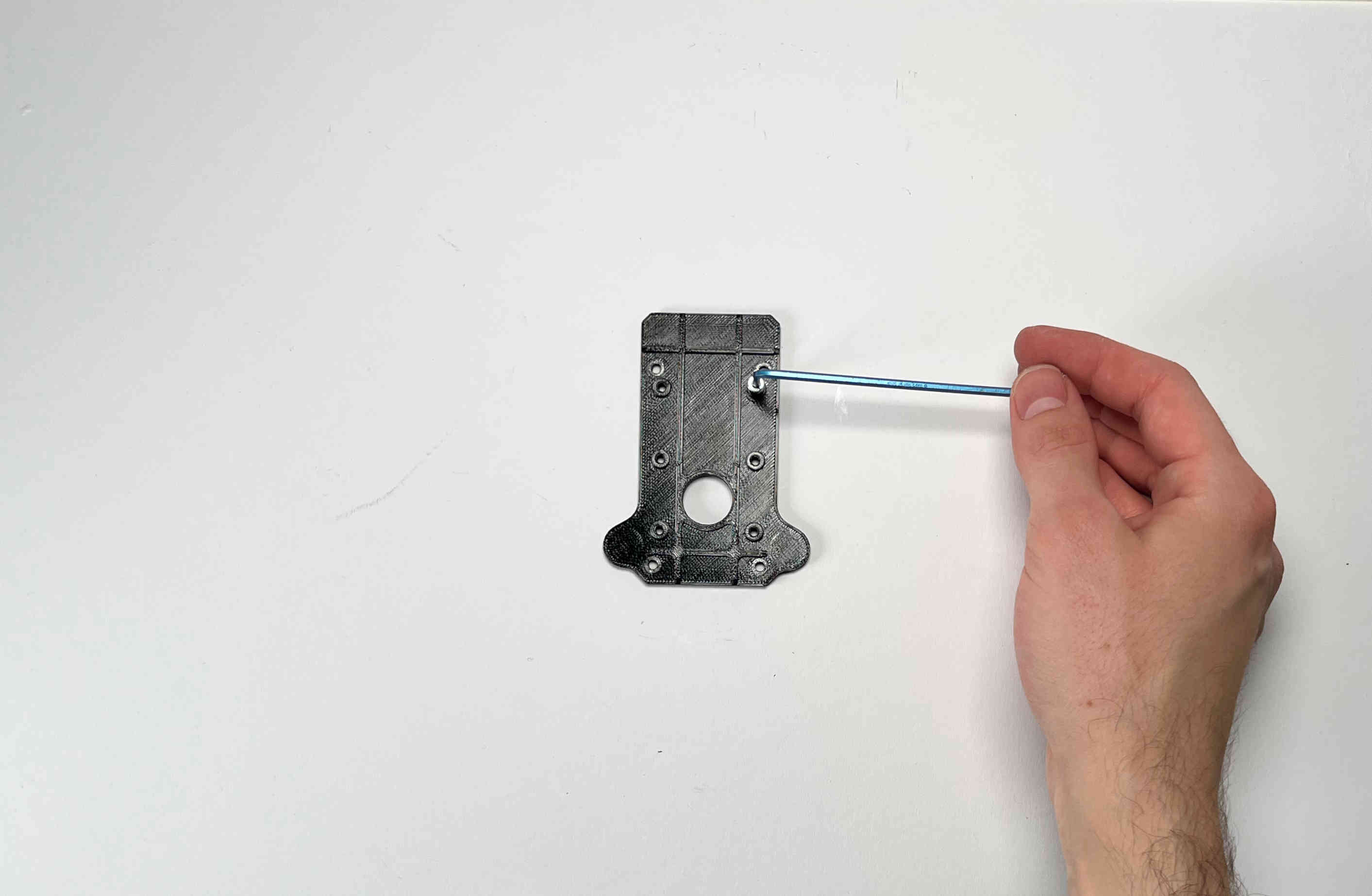
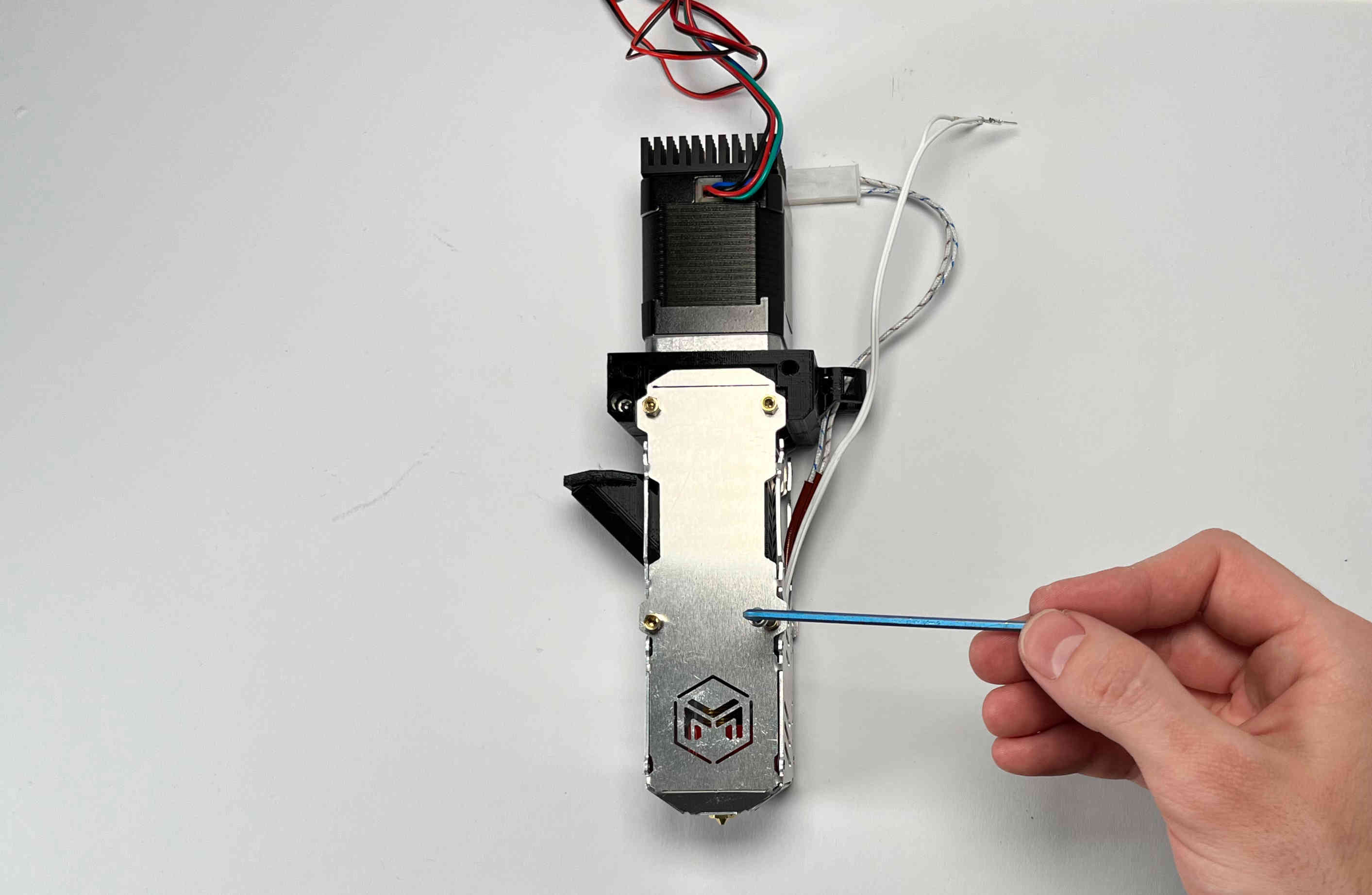
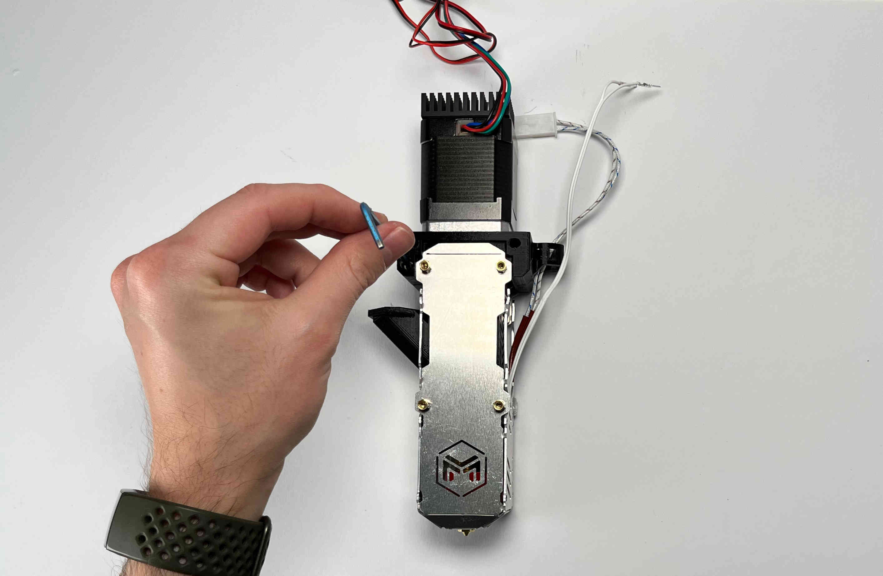
Tap into the plastic part using an M3 screw. (We recommend using a caphead screw to do this to avoid damaging the screw or allen key)
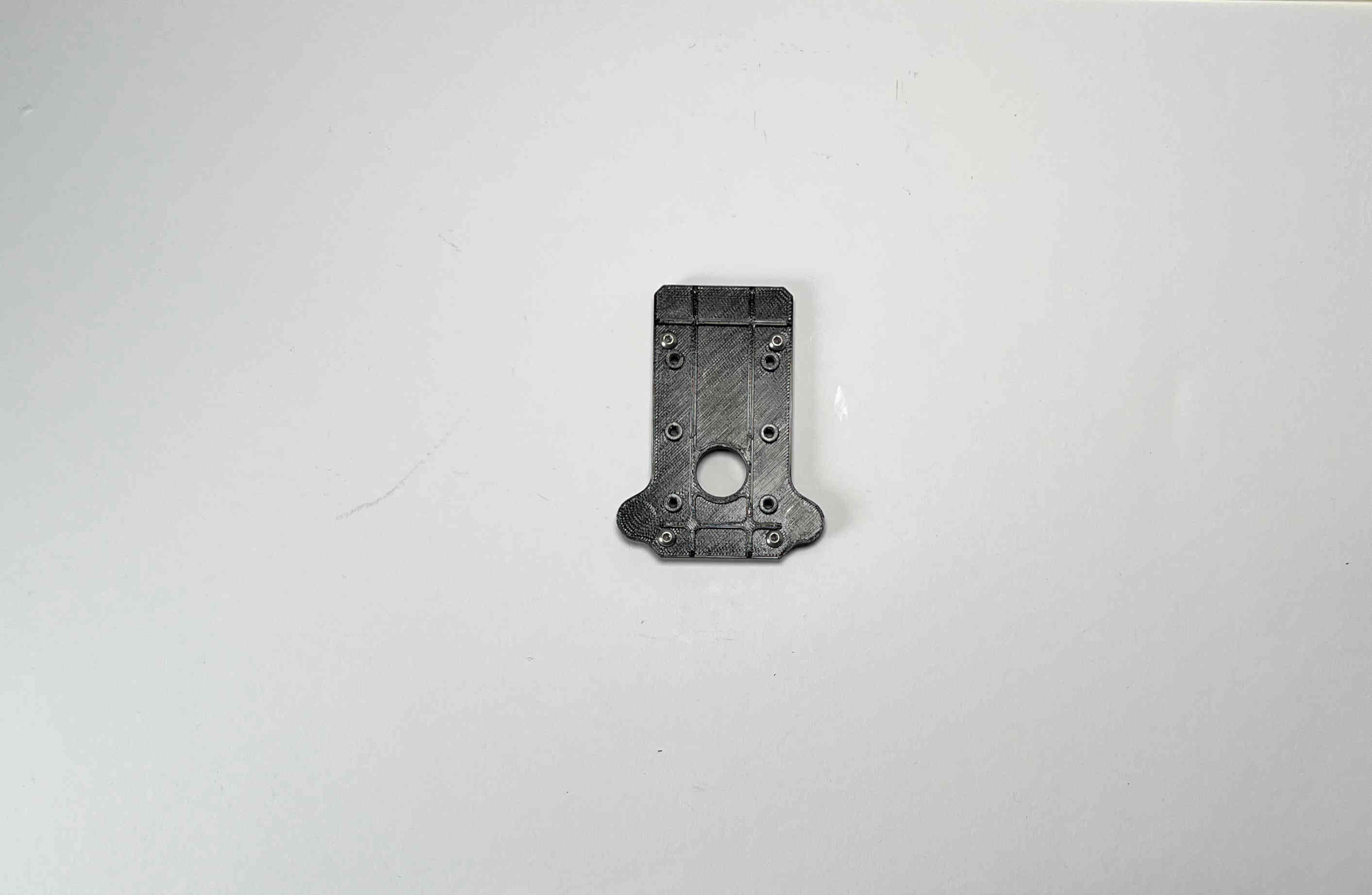
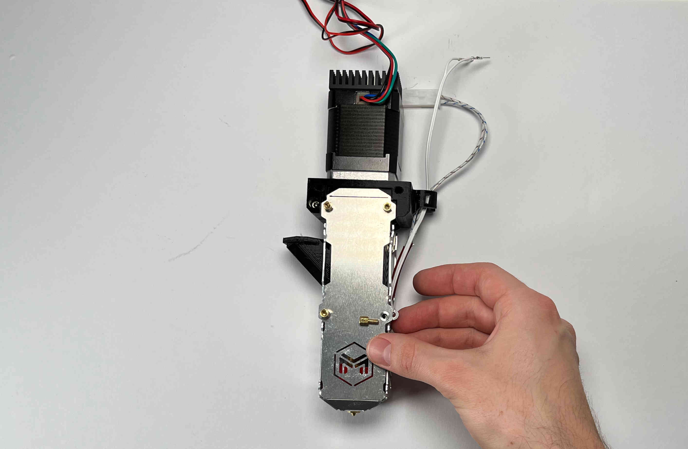
Insert the M3 screws from the pellet extruder in the pellet_plate.
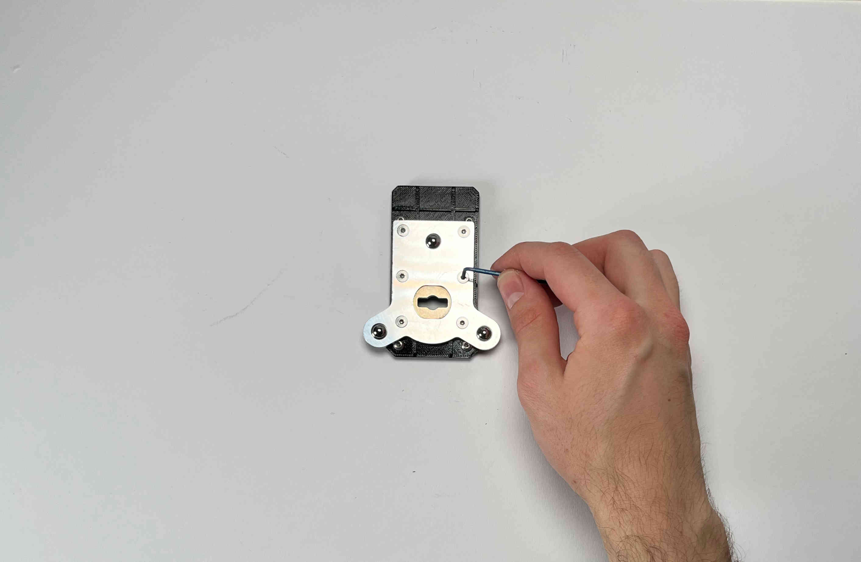
Place the toolplate on the pellet_plate and fasten it using the tapped holes and screws provided by E3D.
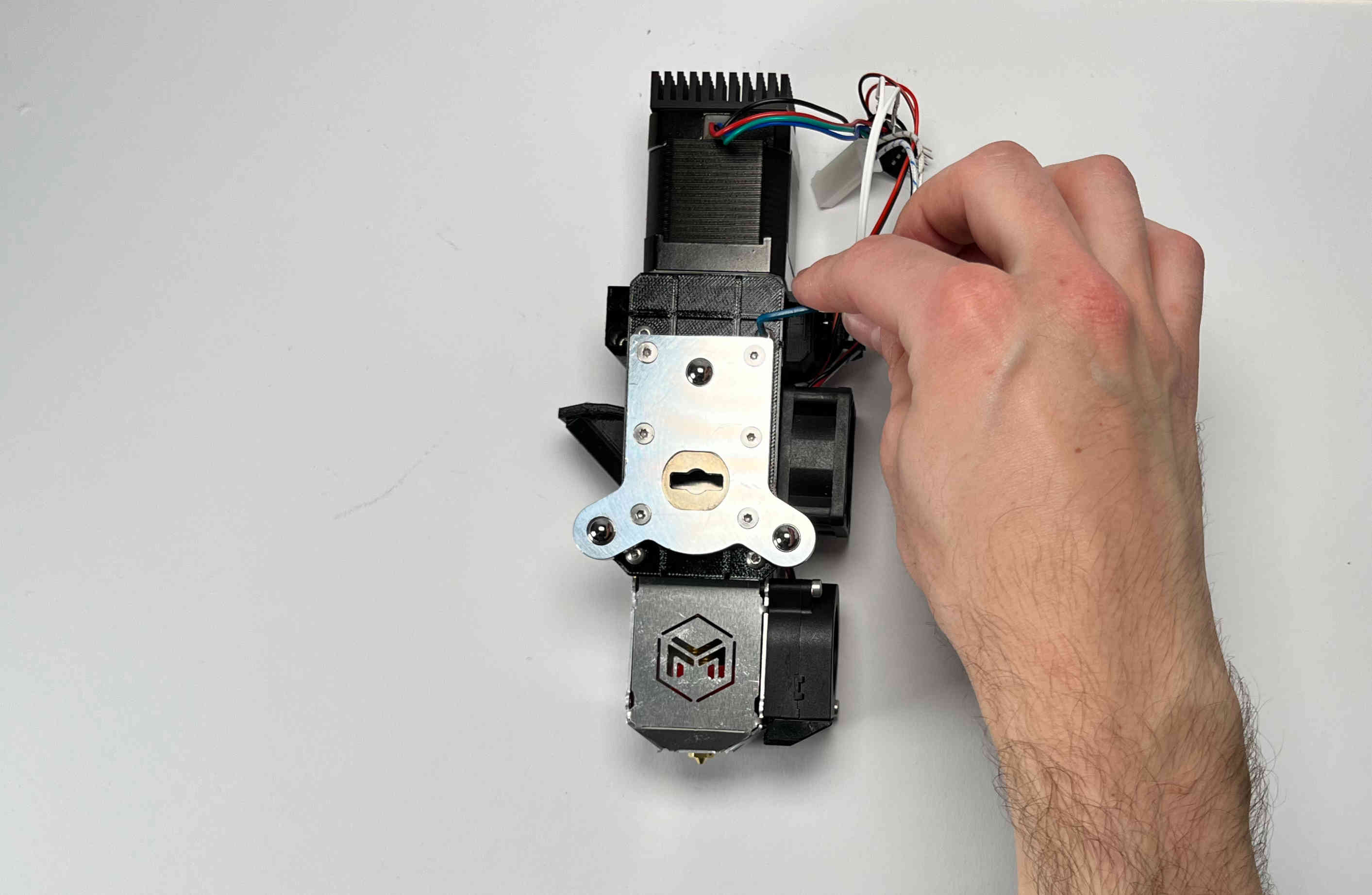
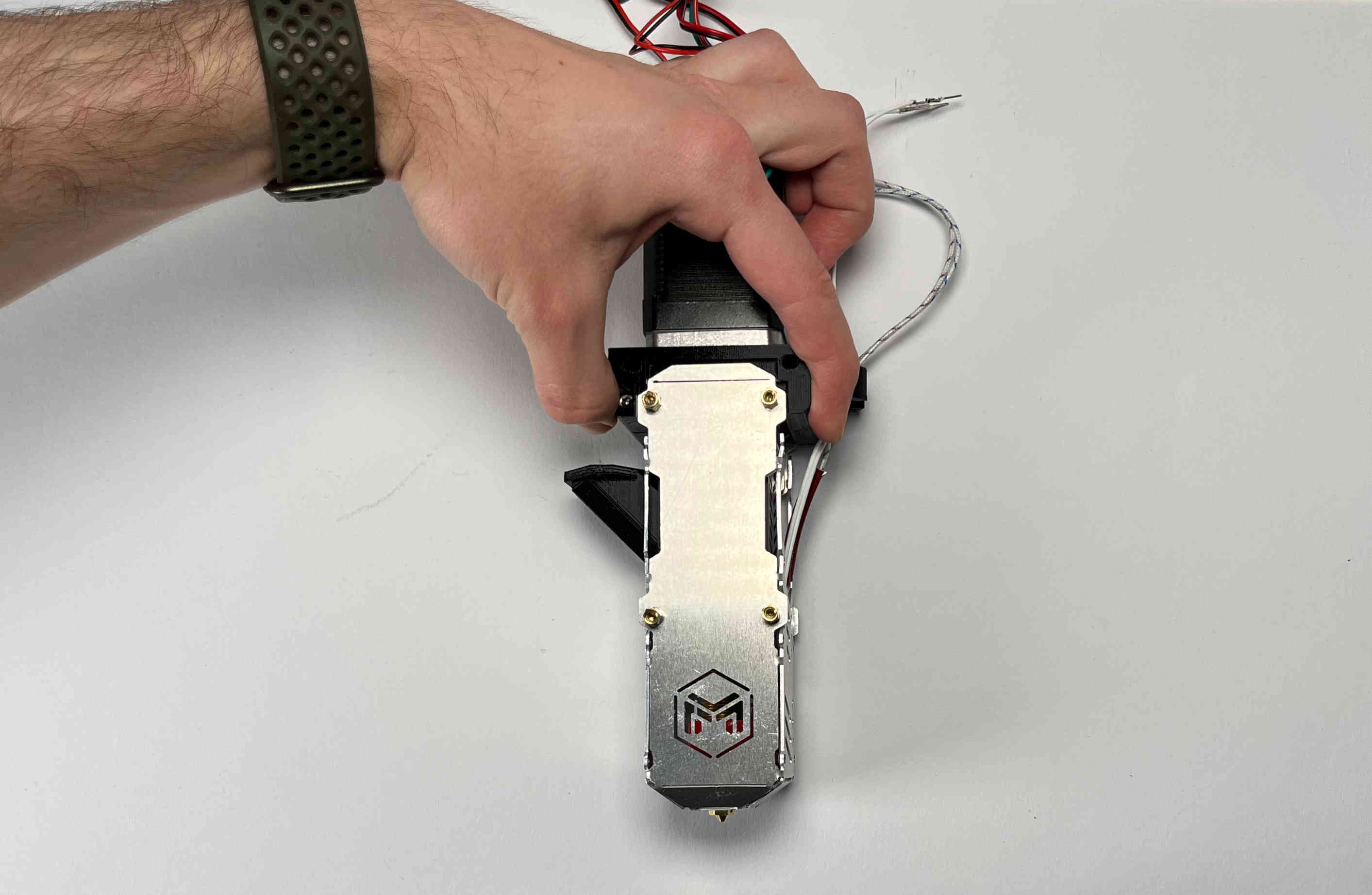
Fasten the plates onto the extruder using the standoffs.
Congratulations! Your Pellet Extruder V4 is ready to be mounted on the Hydra MK1.
We recommend shortening the cables and crimping connectors on the ends. This is so the printhead can easily be removed from the machine for maintenance.